(→Trivia) |
XYZA40479@legacy41486840 (talk | contribs) |
||
| Line 1: | Line 1: | ||
| − | {{ |
+ | {{Mcrs_diagrams}} |
| + | {{about|advanced Redstone circuitry|the ore|Redstone (Ore)|the item|Redstone Dust|the wire|Redstone (Wire)|the torch|Redstone (Torch)}} '' For the repeater, see [[Redstone Repeater]].'' |
||
| + | '''Redstone circuitry''' is a feature introduced in [[Alpha]] which allows for intricate [[Redstone (Wire)|Redstone wire]] based mechanisms to be created by players. |
||
| − | {{Entity |
||
| − | |health={{hp|4}} |
||
| − | |damage={{hp|0}} (only pushes mobs back) |
||
| − | {{hp|3}} to [[Blaze]] |
||
| − | |spawn=Anywhere [[The Player]] chooses |
||
| − | |id=97 |
||
| − | |entityid=SnowMan |
||
| − | |firstver=Beta 1.9 Pre-release |
||
| − | |drops={{ItemLink|Snowball}} (10-15) |
||
| − | |exp=0 |
||
| − | }} |
||
| + | Redstone circuitry is similar to [[Wikipedia:Digital Electronics|digital electronics]] (based on [[Wikipedia:Boolean algebra (logic)|boolean algebra]]) in real life. |
||
| − | A '''Snow Golem''' is the game's first "utility mob", defined by Notch as any player created mob.<ref>http://www.reddit.com/r/Minecraft/comments/kml6r/notchs_new_snowman_mob_is_craftable_and_throws/c2lhmgx</ref> Snow Golems are created using [[Pumpkin]]s and [[Snow (Block)|Snow Blocks]]. Snow Golems will throw [[snowball]]s at enemy mobs and will melt in warmer [[Biomes]]. In cold biomes, they will not melt even when [[lava]] is near them, unless they fall in it. As Snow Golems move, they leave a trail of [[snow]] on the ground (but not in deserts or in [[the Nether]]).<ref>http://twitter.com/notch/status/116449906658516992</ref><ref>http://twitter.com/notch/status/116449606983880705</ref> Snow Golems will not leave snow over blocks such as Redstone dust or torches, but they will wreck farmland by walking on it, and then put snow on the dirt. Once killed, the Snow Golem will drop approximately 10 snowballs. |
||
| + | It's also possible to use [[Tutorials/Piston circuits|pistons]] in redstone circuits. |
||
| − | ==History== |
||
| + | <div style="padding-left: 8px; float: right">__TOC__</div> |
||
| − | The Snow Golem<ref>http://twitter.com/notch/status/116519117586046977</ref><ref>http://www.reddit.com/r/Minecraft/comments/kmro7/mojang_potentially_releasing_something_tomorrow/c2li04x</ref> (previously and colloquially known as a Snowman) is a [[Mobs|mob]] which was first mentioned by [[Notch]] on September 21, 2011 to appear in Beta 1.9, but now officially appears in [[Minecraft 1.0]] since the 1.9 versions were all Pre-releases. |
||
| + | ==Basic mechanics== |
||
| − | In ''[[Minecraft:The Story of Mojang|The Story of Mojang]]'', Notch briefly mentioned about adding "snowmen that throw snowballs." |
||
| + | ===Redstone wire=== |
||
| − | Notch originally planned to call this mob Snowmen. However, very soon after revealing the name, he came upon an entry by the Reddit user "Cuttleman" stating he would call them Snow Golems.<ref>http://www.reddit.com/r/Minecraft/comments/kml6r/notchs_new_snowman_mob_is_craftable_and_throws/c2lhh14</ref> Notch immediately decided to change their title to this.<ref>http://twitter.com/notch/status/116519117586046977</ref> |
||
| + | Redstone wire acts as a power conductor. |
||
| + | Power will travel through 15 blocks of wire. |
||
| + | To place redstone wire, right-click on a block while holding redstone dust. |
||
| + | Note that redstone can't be placed on glass, glowstone, pistons, sticky pistons, TNT, Cake And wooden doors! |
||
| − | == |
+ | ===Powering blocks=== |
| − | [[File:SnowGolemBehavior.png|thumb|A group of Snow Golems throwing snowballs at a spider.]] |
||
| − | Snow Golems throw snowballs at hostile mobs, provoking them. This gives them an almost suicidal nature - snowballs do not do significant damage (except to [[Blaze]]s), but they attract enemies which can kill it or the player. In normal world this makes the Snow Golem useful only for tricking enemies into traps and for distracting them from chasing after the player. In Beta 1.9 Pre-release, Snow Golems sometimes forget to attack monsters. Snow Golems have good pathing skills; they will not attempt to jump off cliffs or into lava. They will attempt to move towards hostile mobs, and even go through open doors to reach them. As of 1.0.0, Snow Golems can open doors.<ref>http://twitter.com/notch/status/116503889959849985</ref> |
||
| + | Some blocks in Minecraft may be powered or unpowered. Think of a "powered block" as a cube of dirt or an empty space (though no truly empty [[Air]] block can be powered) that is invisibly electrified but safe to touch. |
||
| − | == Creating == |
||
| − | {{FakeImage|{{BlockGrid|p=pumpkin|s=snow|p|s|s}}|Snow Golem build configuration}} |
||
| − | To create a Snow Golem, the player must vertically stack two [[Snow (Block)|Snow Blocks]] on the ground, then place a [[Pumpkin]] on top of it. They are not made on the [[Crafting Table]]. They are only created when the pumpkin is placed last. [[Piston]]s cannot create Snow Golems because they cannot push pumpkin blocks. Snow Golems can also be created using a [[Jack-O-Lantern]], although there is no visual difference. [[Endermen]] are also capable of creating Snow Golems by placing the necessary blocks, although this is extremely unlikely to occur naturally. If the snow blocks and pumpkin were placed in 1.8 or earlier versions, they will not become a Snow Golem upon updating. <ref>http://www.reddit.com/r/Minecraft/comments/korjk/endermen_can_make_snow_golems/</ref> |
||
| + | Power may be transmitted from a powered block to one or more of the six directly adjacent blocks. To transmit power, a block must be either: |
||
| − | == Uses == |
||
| + | * an active power source (a [[Redstone (Torch)|redstone torch]]), |
||
| − | Snow Golems may be used for home defense systems if a placed on a 3 block high tower, and surrounded with fence. If a lava moat is placed around the tower, monsters that come to attack the Snow Golem may fall in and die. However, you gain no recources from this. |
||
| + | * the block to which a [[switch]] is attached (that is, the block under a [[pressure plate]] or the block on which a [[lever]] or [[button]] is mounted), |
||
| − | === Farming === |
||
| + | * the block a [[switch]] is in, |
||
| − | Because Snow Golems leave a constant trail of [[snow]] as they move, it is possible to farm that snow. However, due to their behavior of attacking hostile mobs, it would be wise to ensure the Snow Golem is in an enclosed, safe place before beginning. The simplest method is to create a 1x1 hole that is 2 blocks deep, and to put both the player and the Snow Golem in. Then the player would look straight down and farm the snow that is produced. This creates an infinite amount of snow in the shortest time possible, because the instant the snow breaks, another one spawns in its place. |
||
| + | * the block above a [[Redstone (Torch)|redstone torch]] |
||
| + | * an active power conductor ([[Redstone (wire)|redstone wire]] that is immediately adjacent to a powered block). |
||
| + | One must be careful to note that a redstone torch placed on the side of a block of dirt is actually part of the block ''next'' to the dirt, not part of the dirt block itself. Similarly, redstone wire that is placed on top of a block of dirt is part of the block ''above'' the dirt. However, if the block on which the redstone wire is placed becomes powered in any way, so does the redstone wire. |
||
| + | Each actively powered block transmits power in several directions, depending on the contents of the block: |
||
| − | It is also possible to create a generator by placing 2 blocks of snow on a stone then surrounding the top block with any resource. Once this is done, place a pumpkin on top and start digging at the corner of the block where the snow is being generated. Holding down the mouse is the fastest way to gather. |
||
| + | * A redstone torch powers itself and the block directly above it, unless that block is air. Because of how redstone wires work, this also activates adjacent power conduits ([[Redstone (wire)|redstone wire]]). |
||
| − | '''DOES NOT WORK ON 1.0.0''' |
||
| + | * A pressure plate activates the block it is physically located in, as well as the block below (on which it is placed). |
||
| + | * A lever powers the block in which it is located and the block on which it is placed. |
||
| + | * A button powers the block in which it is located and the block on which it is placed. |
||
| + | * [[Redstone (Wire)|Redstone wire]] powers itself, the block below it, the block it is pointing to and the block below that. |
||
| + | ===Redstone wire and signal strength=== |
||
| − | === Defense === |
||
| − | A horde of Snow Golems kept between two lines of fences provides a wall that keeps mobs at a distance. The Snow Golems will still be killed by [[Skeletons]]. A 1x1x2 area can be used to store a horde of Snow Golems. In an emergency the Golems can be released to push back an approaching enemy. |
||
| − | Also efficient is putting Snow Golems In "Guard Towers" up in the air, to keep certain mobs from damaging the Snow Golems. To create a guard tower, make a small 3x3, 1-4 block high tower. fence in the top and create a Snow golem in the center. A favorite design for a tower is 4 blocks high, with blocks all around the fourth block. Then put fence all around the top of the fourth layer, creating a 5th layer. Create the snow golem on the one block in the fence. Stack 2 fence 2 blocks away from the base of the tower to keep mobs from taking refuge under the tower. |
||
| + | Whether a block is weakly or normally (strongly) powered affects how redstone wires interact with it. |
||
| − | === Lure === |
||
| + | Blocks are strongly powered by redstone power sources; torches (from below), repeaters, levers, pressure plates etc. If a block is powered only by redstone wire then it is weakly powered. |
||
| − | Snow Golems can also be used to lure hostile mobs into traps intended for them. This can create a better flow of mob drops for the player to collect, speeding up mob harvesting. This can be something such as fencing in Snow Golems just beyond the trap's entrance, having the mobs wander in as they attempt to attack the Snow Golems and dying. |
||
| + | Redstone wire which is adjacent to, on top of, or below a block that is strongly powered will become active. It will not become active if that block is weakly powered. |
||
| + | ===Powering devices=== |
||
| − | The player can also fence in multiple Snow Golems 2 wide above a pit of lava 2 deep. As this won't melt them, they will be free to provoke mobs into falling into the trap, passively protecting the player's work area. These methods can also keep mobs from hiding around the player's home. |
||
| + | A device, such as a [[door]], a [[minecart track]], or a block of [[TNT]], is activated when an adjacent block is powered. As a simple example, placing a redstone torch next to a door will change the state of the door to on. Similarly, standing on a pressure plate immediately adjacent to a door will activate the door. However, standing on a pressure plate two blocks away from a door will not activate the door, because the power does not reach the block next to or under the door. |
||
| − | A single Snow Golem kept between four fences under a 3x3 two blocks high ceiling can be used to distract attacking Endermen. Once the Enderman is within reach of the Snow Golem, the Golem will pelt it with snowballs. The Endermen will stop attacking the player, but will be unable to reach the Snow Golem due to the ceiling. A moat filled with lava or water around the Snow Golem enclosure can be used to kill the Endermen instead of simply distracting them. |
||
| + | To power devices at a distance, the power must be conducted from the active power source to the device; redstone wire is used for this purpose. As noted above, the redstone wire is part of the block it is physically located in, ''not'' the block to which it is attached. Redstone wire, or dust, has two states: on (lit) and off (unlit). |
||
| − | === Distance Triggering === |
||
| − | By placing a Pressure Plate inside the fenced area mentioned above, the Snow Golem can be used to activate traps as well. Note that Creepers, Spiders, Cave Spiders, Skeletons, Spider Jockeys, and Magma Cube traps are not advised for this. |
||
| + | The simplest way to activate redstone wire is to put a redstone torch or switch adjacent to the wire. It also works to have a torch or switch directly above the wire, attached to a wall. |
||
| − | == Gallery == |
||
| − | <gallery> |
||
| − | File:SnowmanMob1.png|First screenshot of this mob, released by Notch in September 21st, 2011. |
||
| − | File:SnowGolemAndMoon.png|A snow golem with a moon in the background. |
||
| − | File:endermadegolems.jpg|Three snow golems that were built by Endermen. |
||
| − | File:insidetheman.png|The view from inside a snow golem, proving that the regular head still is in the game. |
||
| − | File:2011-10-26 14.04.37.png|Snow golems in a body of water. |
||
| − | File:Baby golem.png|A successfully bred Snow Golem before 1.0. |
||
| + | A redstone torch is itself a powered device; its default state is "on", but it will be turned off if it receives power from the block to which it is attached. This feature, along with the use of wire to transmit power in particular directions over distance, is the basis for the advanced redstone devices and circuitry below. |
||
| − | </gallery> |
||
| + | Care must be taken to follow the power rules precisely, or one might see unexpected results. For example, consider a pressure plate. Activating the plate will power the block underneath the plate as well as the block in which the plate resides. Nevertheless, redstone wire ''beneath'' this block will still be powered, because it is adjacent to the powered block above it. However, activating the plate will not turn off a redstone torch placed beneath the powered block -- in fact, placing a redstone torch under the block under the pressure plate will power it continuously, effectively disabling the plate. |
||
| − | == Bugs == |
||
| − | *Snow Golems do not leave snow trails in Mushroom Biomes. |
||
| − | *Snow Golems can be built in The Nether. This would not appear to be intended, considering other forms of water either melt or evaporate there. However, blazes may be killed by snowballs. |
||
| − | *In SMP, Snow Golems do not make a sound when throwing a snowball. |
||
| − | *In Beta 1.9 Pre-release 2, Snow Golems will start attacking the player if he/she holds [[Wheat]]. This is presumably because Snow Golems might have the command to attack within their follow command, and the new Breeding system makes "passive" mobs follow entities. This also applies to their being in Love Mode; whereas they will begin following each other and cause themselves to attack, thus disabling their Love Mode and causing them to flee from one another. |
||
| − | *In Beta 1.9 Pre-release 3, in SMP, Snow Golems have become invisible but were still able to be killed. This was fixed in Beta 1.9 Pre-release 5 |
||
| − | **In Beta 1.9 Pre-release 4 however this is partially fixed. However it doesn't seems to be working in [[The End|the End]] {{Citation needed}} |
||
| − | * In Minecraft 1.0 snowgolems can multiply if placed in a small tower, this bug is common for those who build snowgolem towers. |
||
| + | ===Specific powered devices=== |
||
| − | == Trivia == |
||
| + | Certain devices act in specific ways, for example: |
||
| − | *Snow Golems do not de-spawn if the player leaves the area. |
||
| + | * If a block is powered, a redstone torch attached to it will be deactivated. |
||
| − | * Snow Golems completed by a piston do not come to life. It is unclear whether this is a bug. |
||
| + | * If a block is powered, a door on top of it or adjacent to it will toggle its state from open to closed or vice versa. (The actual state will depend, because doors were implemented unintuitively.) |
||
| − | * A couple hundred snowmen can in fact kill mobs, but will understandably take quite a while and result in heavy losses. |
||
| + | * If a block is powered, and it is a note block/dispenser, it will play/shoot once. |
||
| − | * Snow Golems are the second mob the player can spawn themselves. The first one is [[Chicken]]s spawning from [[Egg]]s thrown by the player. |
||
| + | * If a block is powered, and rails are above it, they will toggle shape. (You can still have the wiring power the rail directly.) |
||
| − | * Four Snow Golems throw snowballs at a fast enough rate to continuously push a Zombie back. |
||
| − | * On Reddit, Notch stated that the Snow Golem is the first "Utility Mob"; a mob that the player can create for their own convenience.<ref>http://www.reddit.com/r/Minecraft/comments/kml6r/notchs_new_snowman_mob_is_craftable_and_throws/c2lhmgx</ref> |
||
| − | * Snow Golems are not affected by fall damage. It is unknown if this is a bug. |
||
| − | * Snow Golems wear their Pumpkin as a hat. Their actual Snowman-type head is hidden beneath it. |
||
| − | * If a Snow Golem is lit on fire, it will speed up and move toward a water source. |
||
| − | * Snow Golems do not attack aggressive wolves even if they attack the player. |
||
| − | * Snow Golems will attack [[Zombie Pigman|Zombie Pigmen]] regardless of whether or not they attacked the player, thus making the whole pack attack them. |
||
| − | * Snow Golems sometimes survive [[creeper]] explosions. |
||
| − | * The throwing sound is actually the [[Bow]] firing sound, even though Snowballs have their own throwing sound. |
||
| − | * Snow Golems don't leave a snow trail in the nether, probably because they melt. |
||
| − | * If a Snow Golem is trapped somewhere and there is an exit, the Snow Golem will try to escape, immediately heading for the exit. |
||
| − | * Snow Golems ''do'' leave a trail of snow in [[The End]]. |
||
| − | * Since the full release, (1.0) Snow Golems no longer have the ability to breed. This is possibly due to the fact the snow golems attack each other when in love mode. |
||
| − | * Snow Golems can only be crafted by placing a pumpkin on top of two snow blocks, placing the pumpkin then snow under it will result in failure. |
||
| − | *If trapped underwater, Snow Golems CAN drown, despite not being alive. |
||
| + | ===Common errors to avoid=== |
||
| − | == References == |
||
| + | The following are common errors to avoid: |
||
| − | <references/> |
||
| + | * Trying to transmit power through a block that doesn't have any redstone wire on it. While a generic block (dirt, sand, gravel, etc.) adjacent to the end of a wire can ''receive'' power, it will not ''transmit'' that power to wire on the other side, because it is not one of the blocks that can transmit power. If you have a block that you cannot move, send wire around it (including on top of it). Alternatively, you can put a repeater on the side transmitting power, as repeaters can send power through blocks (see below). |
||
| + | * If a block has redstone wire on top and a redstone torch on the side, then the block above the torch must be either air, glass or a half-tile (unless you know what you're doing). If you place any solid block above the torch, it will create a feedback loop and the torch will probably burn out. |
||
| + | ==Logic gates== |
||
| − | {{Entities}} |
||
| + | A logic gate can be thought of as a simple device that will return a number of ''outputs'', determined by the pattern of ''inputs and rules'' that the logic gate follows. For example, if both inputs in an [[#AND Gate (∧)|AND]] gate are in the 'true'/'on'/'powered' state, then the gate will return 'true'/'on'/'powered'. Much more in-depth information and a better explanation of this expansive topic is available on [[Wikipedia:Logic gate|Wikipedia]]. |
||
| − | [[Category:Neutral mobs]] |
||
| + | Below is a list of some of the basic gates with example images and [http://www.minecraftforum.net/viewtopic.php?f=25&t=17924 MC Redstone Sim] diagrams. There are many different ways to construct them other than those shown below, so use them as guidelines for creating one to fit your needs. Most circuits have multiple valid implementations, with various advantages and disadvantages between designs such as size, complexity, performance, maintenance overhead. |
||
| − | [[de:Schneegolem]] |
||
| + | |||
| − | [[fr:Golem de neige]] |
||
| + | Keep in mind that : |
||
| − | [[pl:Bałwan]] |
||
| + | * [[tick]] is the delay between the events "redstone torch receives power" and "redstone torch turns off or on". (depending on its initial state); |
||
| − | [[ru:Снежный голем]] |
||
| + | * repeaters can be set to 1,2,3,4 tick(s). One tick = 0.1 seconds. |
||
| + | * The rapid pulser is ''too fast for repeaters''. |
||
| + | |||
| + | {{#ev:youtube|xJ-NQdCxrXs}} |
||
| + | |||
| + | <!--TODO--> |
||
| + | [[Image:StandardLogicGates.png|thumb|400px|none|Basic logic gate diagrams]] |
||
| + | {{-}} |
||
| + | |||
| + | ===Piston circuits=== |
||
| + | [[Tutorials/Piston circuits|Piston circuits]] are circuits featuring logic gates created with [[piston]]s that are ''in some cases'' smaller and more compact than traditional logic gates. |
||
| + | Some circuits, such as a 0.5 tick on and 0.5 tick off clock, need pistons. |
||
| + | |||
| + | ===Circuit symbols=== |
||
| + | Each symbol represents one to three blocks (most often one or two), viewed from above. All descriptions are with reference to a "ground level", the level where you are building your gate on. |
||
| + | |||
| + | [[File:Redstone Simulator Guide.png|620px|Symbol guide for Redstone Simulator v2.2]] |
||
| + | |||
| + | From left to right: |
||
| + | #[[Air]]: air over air, i.e. two empty blocks, one above the other above ground level |
||
| + | #[[Block]]: air over a block (of any sort) |
||
| + | #Two Blocks: block over block, i.e. two solid blocks above ground level |
||
| + | #[[Redstone (Wire)|Wire]]: wire (with a block assumed below the wire, below ground level) |
||
| + | #[[Redstone Torch]]: air over redstone torch (all torches are redstone torches in circuits) |
||
| + | #Wire over Block |
||
| + | #Torch over Block |
||
| + | #Block over Wire (i.e.: layer 1 is wire; layer 2 is a block) |
||
| + | #Block over Torch |
||
| + | #Torch over Wire (i.e.: layer 1 is wire; layer 2 is a torch, attached to adjacent layer 2 block not shown) |
||
| + | #Bridge: wire on top of block, over wire (with the usual empty air block above the top wire, see [[Redstone schematics]]) |
||
| + | #[[Lever]] (aka Switch): air over switch |
||
| + | #[[Stone Button]]: air over button (button lasts 10 ticks) |
||
| + | #[[Pressure Plate]]: air over plate |
||
| + | #[[Door]]: 2-high |
||
| + | #Shadow |
||
| + | #[[Redstone Repeater|Repeater]]: air over a repeater on any setting, also represents repeater on ground in vertical diagrams |
||
| + | #Repeater over Block |
||
| + | #Block over Repeater |
||
| + | #[[Dispenser]] |
||
| + | #[[Dispenser]] on top of a block |
||
| + | #A block on top of a [[dispenser]] |
||
| + | #Air over a [[sticky piston]] |
||
| + | #Air over a [[piston]] |
||
| + | #A [[sticky piston]] on top of a block of any kind |
||
| + | #A [[piston]] on top of a block of any kind |
||
| + | #A block of any kind on top of a [[sticky piston]] |
||
| + | #A block of any kind on top of a [[piston]] |
||
| + | {{-}} |
||
| + | |||
| + | |||
| + | ===NOT gate (¬)=== |
||
| + | [[Image:NOT gate.gif|frame|NOT gate (inverter)]] |
||
| + | A device that inverts the input, as such it is also called an "Inverter" Gate.<br /> |
||
| + | |||
| + | {| class="wikitable" style="float: left; text-align:center" |
||
| + | ! A !! ¬A |
||
| + | |- |
||
| + | | 1 || 0 |
||
| + | |- |
||
| + | | 0 || 1 |
||
| + | |} |
||
| + | {| class="wikitable" style="float: left;" |
||
| + | ! Design !! A !! B |
||
| + | |- |
||
| + | | Size || 1x1x2 || 1x2x1 |
||
| + | |- |
||
| + | | Torches || 1 || 1 |
||
| + | |- |
||
| + | | Redstone || 0 || 0 |
||
| + | |- |
||
| + | | Input isolated? || Yes || Yes |
||
| + | |- |
||
| + | | Output isolated? || Yes || Yes |
||
| + | |} |
||
| + | {{-}} |
||
| + | |||
| + | ===OR gate (∨)=== |
||
| + | [[Image:OR gate.gif|thumb|Three-input OR gate]] |
||
| + | A device where the output is on when at least one of the inputs are on. |
||
| + | |||
| + | A simpler version of the OR gate is design '''A''': merely a wire connecting all inputs and outputs. However, this causes the inputs to become "compromised", so that they can only be used in this OR gate. If you need to use the inputs elsewhere, either torches (version '''B''') or repeaters are necessary for isolation. |
||
| + | |||
| + | Version '''C''' can be expanded horizontally up to 14 inputs (limited by signal propagation distance on the "bus" wire) is isolated, and is one tick faster than '''B'''. However, it requires 3 redstone to make each repeater. |
||
| + | |||
| + | Note that design '''B''' is a simple inversion of a NOR gate. |
||
| + | {| class="wikitable" style="float: left; text-align:center" |
||
| + | ! A !! B !! A∨B |
||
| + | |- |
||
| + | | 1 || 1 || 1 |
||
| + | |- |
||
| + | | 1 || 0 || 1 |
||
| + | |- |
||
| + | | 0 || 1 || 1 |
||
| + | |- |
||
| + | | 0 || 0 || 0 |
||
| + | |} |
||
| + | {| class="wikitable" style="float: left;" |
||
| + | ! Design !! A !! B !! C |
||
| + | |- |
||
| + | | Size || 1x1x1 || 1x3x2 || 2x(y+1)x1 |
||
| + | |- |
||
| + | | Torches || 0 || 2 || 0 |
||
| + | |- |
||
| + | | Redstone || 1 || 1 || 7 |
||
| + | |- |
||
| + | | Inputs isolated? || No || Yes || Yes |
||
| + | |- |
||
| + | | Output isolated? || No || Yes || Yes |
||
| + | |- |
||
| + | | Max inputs || 3 || 3 || y |
||
| + | |} |
||
| + | |||
| + | {{-}} |
||
| + | |||
| + | ===NOR gate (⊽)=== |
||
| + | [[Image:NOR gate.gif|thumb|NOR gate designs.]] |
||
| + | A device where the output is off when at least one of the inputs are on. All logic gates can be made from either this gate or the NAND gate. In Minecraft, this is the basic logic gate, implemented by a torch. A torch can have as many as 4 mutually isolated inputs (design '''B'''), but 3 can fit comfortably (design '''A'''), and all are optional. A torch with 1 input is the NOT gate, and with no inputs is the TRUE gate (i.e. a power source). If more inputs than 4 are necessary, one must resort to the non-isolated OR gate with a NOT at the end (at expense of isolation), or multiple NOR gates, according to the formula ''A'' ⊽ ''B'' ⊽ ''C'' = ''A'' ⊽ ¬(''B'' ∨ ''C'') (at the expense of speed, due to the nested gates).<br /> |
||
| + | |||
| + | {| class="wikitable" style="float: left; text-align:center" |
||
| + | ! A !! B !! A⊽B |
||
| + | |- |
||
| + | | 1 || 1 || 0 |
||
| + | |- |
||
| + | | 1 || 0 || 0 |
||
| + | |- |
||
| + | | 0 || 1 || 0 |
||
| + | |- |
||
| + | | 0 || 0 || 1 |
||
| + | |} |
||
| + | {| class="wikitable" style="float: left" |
||
| + | ! Design !! A !! B |
||
| + | |- |
||
| + | | Size || 1x1x2 || 3x3x3 |
||
| + | |- |
||
| + | | Torches || 1 || 1 |
||
| + | |- |
||
| + | | Redstone || 0 || 5 |
||
| + | |- |
||
| + | | Inputs || 3 || 4 |
||
| + | |- |
||
| + | | Inputs isolated? || Yes || Yes |
||
| + | |} |
||
| + | {{-}} |
||
| + | |||
| + | {{#ev:youtube|SUUJrFC-Uk0}} |
||
| + | |||
| + | ===AND gate (∧)=== |
||
| + | [[Image:AND gate.gif|thumb|AND gate designs.]] |
||
| + | A device where the output is on when both inputs are on. This behaves in a manner equivalent to a Tri-state buffer, where input ''B'' acts like a switch, so that if it is off, input ''A'' is disconnected from the rest of the circuit. The discrepancy from real-life tri-state buffers lies in the fact that one cannot drive a low current in Minecraft. (See the Wikipedia article for details.) |
||
| + | |||
| + | An example application would be building a locking mechanism for a door, requiring both the activating button and the lock (typically a lever) to be on.<br /> |
||
| + | |||
| + | {| class="wikitable" style="float: left; text-align:center" |
||
| + | ! A !! B !! A∧B |
||
| + | |- |
||
| + | | 1 || 1 || 1 |
||
| + | |- |
||
| + | | 1 || 0 || 0 |
||
| + | |- |
||
| + | | 0 || 1 || 0 |
||
| + | |- |
||
| + | | 0 || 0 || 0 |
||
| + | |} |
||
| + | {| class="wikitable" style="float: left" |
||
| + | ! Design !! A !! B !! C |
||
| + | |- |
||
| + | | Size || 3x2x2 || 2x3x2 || 1x6x5 |
||
| + | |- |
||
| + | | Torches || 3 || 3 || 3 |
||
| + | |- |
||
| + | | Redstone || 1 || 2 || 3 |
||
| + | |} |
||
| + | {{-}} |
||
| + | |||
| + | ===NAND gate (⊼)=== |
||
| + | [[Image:NAND gate.gif|thumb|NAND gate designs.]] |
||
| + | A device where the output is off when both inputs are on.<br /> |
||
| + | |||
| + | {| class="wikitable" style="float: left; text-align:center" |
||
| + | ! A !! B !! A⊼B |
||
| + | |- |
||
| + | | 1 || 1 || 0 |
||
| + | |- |
||
| + | | 1 || 0 || 1 |
||
| + | |- |
||
| + | | 0 || 1 || 1 |
||
| + | |- |
||
| + | | 0 || 0 || 1 |
||
| + | |} |
||
| + | {| class="wikitable" style="float: left" |
||
| + | ! Design !! A !! B |
||
| + | |- |
||
| + | | Size || 3x1x2 || 2x2x1 |
||
| + | |- |
||
| + | | Torches || 2 || 2 |
||
| + | |- |
||
| + | | Redstone || 1 || 1 |
||
| + | |} |
||
| + | {{-}} |
||
| + | |||
| + | ===XOR gate (⊻)=== |
||
| + | [[Image:XOR gate.gif|thumb|XOR gate designs (click to see it animated).]] |
||
| + | <!-- other diagram below the tables to make it work --> |
||
| + | XOR is a device which activates when the inputs are not the same, when only one is on. XOR is pronounced "exor," and is a shortening of "exclusive or," because it's OR excluding when both inputs are true. The output will turn when exactly 1 of the inputs is on. Adding a NOT gate to the end will produce an XNOR gate, which activates when the inputs are equal to each other. A useful attribute is that an XOR or XNOR gate will always change its output when one of its inputs changes, allowing for 2 switches to be combined to open or close a door, or activate another device. |
||
| + | |||
| + | Design D is not useful unless you want the levers to be fixed to the circuit. Design F is the most widely used. |
||
| + | |||
| + | When using Design F it should be noted that a solid block must be placed over each of the two redstone torches that are not attached to the side of a block, as shown in the diagram at right. |
||
| + | |||
| + | {| class="wikitable" style="float:left; text-align:center" |
||
| + | ! A !! B !! A⊻B |
||
| + | |- |
||
| + | | 1 || 1 || 0 |
||
| + | |- |
||
| + | | 1 || 0 || 1 |
||
| + | |- |
||
| + | | 0 || 1 || 1 |
||
| + | |- |
||
| + | | 0 || 0 || 0 |
||
| + | |} |
||
| + | {| class="wikitable" style="float: left" |
||
| + | ! Design !! A !! B !! C !! D !! E !! F !! G ! |
||
| + | |- |
||
| + | | Size || 3x5x2 || 3x3x3 || 5x5x1 || 3x3x2 || 5x4x2 || 3x3x3 || 5x2x2 |
||
| + | |- |
||
| + | | Torches || 5 || 5 || 3 || 3 || 3 || 5 || 8 |
||
| + | |- |
||
| + | | Redstone || 6 || 5 || 14 || 3 || 12 || 4 || 4 |
||
| + | |- |
||
| + | | Repeaters|| 0 || 0 || 0 || 0 || 0 || 0 || 0 |
||
| + | |- |
||
| + | | Speed (ticks) || 3 || 3 || 2 || 2 || 2 || 3 || 3 |
||
| + | |- |
||
| + | | Output direction || fwd. || '''rev.''' || fwd. || fwd. || fwd. || fwd. || fwd. |
||
| + | |- |
||
| + | | Requires levers? || No || No || No || '''Yes''' || No || No || No |
||
| + | |} |
||
| + | [[Image:XOR_H.gif|thumb|XOR gate Design H]] |
||
| + | |||
| + | [[Image:XOR F.jpg|thumb|XOR gate Design F]] |
||
| + | {{-}} |
||
| + | |||
| + | ===XNOR gate (≡)=== |
||
| + | [[image:XNOR gate.gif|thumb|upright=1.8|XNOR gate designs (click to see this animated).]] |
||
| + | In logic, this is more commonly referred to as "if and only if" or "iff" for short. It is a device which activates only when the inputs are equal to each other. In other words when either input changes, the output changes. This is achieved by inverting the output or '''one''' input of an XOR. An application of this in Minecraft would be to wire up two levers to the same door.<br /> |
||
| + | |||
| + | {| class="wikitable" style="float: left; text-align:center" |
||
| + | ! A !! B !! A≡B |
||
| + | |- |
||
| + | | 1 || 1 || 1 |
||
| + | |- |
||
| + | | 1 || 0 || 0 |
||
| + | |- |
||
| + | | 0 || 1 || 0 |
||
| + | |- |
||
| + | | 0 || 0 || 1 |
||
| + | |} |
||
| + | {| class="wikitable" style="float: left;" |
||
| + | ! Design !! A !! B !! C !! D !! E !! F |
||
| + | |- |
||
| + | | Size || 4x3x2 || 4x3x2 || 2x5x4 || 3x5x3 || 4x5x2 || 4x5x2 |
||
| + | |- |
||
| + | | Torches || 6 || 4 || 4 || 4 || 4 || 4 |
||
| + | |- |
||
| + | | Redstone || 5 || 5 || 7 || 7 || 10 || 9 |
||
| + | |- |
||
| + | | Speed (ticks) || 3 || 2 || 2 || 2 || 2 || 2 |
||
| + | |- |
||
| + | | Output direction || fwd. || fwd. || fwd. || fwd. || fwd. || '''rev.''' |
||
| + | |- |
||
| + | | Levers required? || No || '''Yes''' || No || No || No || No |
||
| + | |} |
||
| + | {{-}} |
||
| + | |||
| + | ===IMPLIES gate (→)=== |
||
| + | [[Image:IMPLIES.gif|thumb|IMPLIES gate.]] |
||
| + | A device which represents [[Wikipedia:Material conditional|material implication]]. Returns false only if the implication ''A → B'' is false. That is, if the antecedent ''A'' is true, but the consequent ''B'' is false. It is often read "if ''A'' then ''B''." It is the logical equivalent of "B or NOT A". |
||
| + | |||
| + | Design C has a speed of 2 ticks if output is 1, but 1 tick if the output is 0. If you must synchronize the output, consider placing a repeater in front of input A with a 1 tick delay. |
||
| + | |||
| + | {| class="wikitable" style="float: left; " |
||
| + | ! A !! B !! A→B |
||
| + | |- |
||
| + | | 1 || 1 || 1 |
||
| + | |- |
||
| + | | 1 || 0 || 0 |
||
| + | |- |
||
| + | | 0 || 1 || 1 |
||
| + | |- |
||
| + | | 0 || 0 || 1 |
||
| + | |} |
||
| + | {| class="wikitable" style="float: left;" |
||
| + | ! Design !! A !! B !! C !! D |
||
| + | |- |
||
| + | | Size || 2x2x1 || 2x1x2 || 2x3x2 || 1x3x2 |
||
| + | |- |
||
| + | | Torches || 1 || 1 || 3 || 1 |
||
| + | |- |
||
| + | | Redstone || 1 || 1 || 2 || 2 |
||
| + | |- |
||
| + | | Speed (ticks) || 1 || 1 || 2 || 1 |
||
| + | |- |
||
| + | | Inputs isolated? || Only A || Only A || Yes || Only A |
||
| + | |- |
||
| + | | Output isolated? || No || No || Yes || No |
||
| + | |} |
||
| + | {{-}} |
||
| + | |||
| + | ==Latches and flip-flops== |
||
| + | [[Wikipedia:Latch (electronics)|Latches]] and [[Wikipedia:Flip-flop (electronics)|flip-flops]] are effectively 1-bit memory cells. They allow circuits to store data and deliver it at a later time, rather than acting only on the inputs at the time they are given. Functions using these components can be built to give different outputs in subsequent executions even if the inputs don't change, and so circuits using them are referred to as "sequential logic". They allow for the design of counters, long-term clocks, and complex memory systems, which cannot be created with combinational logic gates alone. |
||
| + | |||
| + | The common feature at the heart of every redstone latch or flip-flop is the RS NOR latch, built from two NOR gates whose inputs and outputs are connected in a loop (see below). The basic NOR latch's symmetry makes the choice of which state represents 'set' an arbitrary decision, at least until additional logic is attached to form more complex devices. Latches usually have two inputs, a 'set' input and a 'reset' input, used to control the value that is stored, while flip-flops tend to wrap additional logic around a latch to make it behave in different ways. |
||
| + | |||
| + | ===RS NOR latch and Input Stabilizers=== |
||
| + | [[File:RS NOR latch.gif|thumb|upright=4|RS NOR latch designs.]] |
||
| + | [[File:RS NOR Latch E.gif|thumb|upright=2|RS NOR latch E design.]] |
||
| + | [[File:Vertical RS-NOR.png|thumb|Design H, a compact vertical RS NOR latch ([http://www.minecraftforum.net/viewtopic.?p=1050121#p1050121 Source])]] |
||
| + | [[File:Input Stabilizing Cell (RSNOR Latch Variant).JPG|thumb|RS NOR Latch Variation using a repeater]] |
||
| + | |||
| + | A device where Q will stay on forever after input is received by S. Q can be turned off again by a signal received by R. |
||
| + | |||
| + | This is probably the smallest memory device that is possible to make in Minecraft. Note that <span style="text-decoration:overline">Q</span> means the opposite of Q, e.g. when Q is on, <span style="text-decoration:overline">Q</span> is off and vice-versa. This means that in certain cases, you can get rid of a NOT gate by simply picking the <span style="text-decoration:overline">Q</span> output instead of putting a NOT gate after the Q output. |
||
| + | |||
| + | A very basic example of use would be making an alarm system in which a warning light would stay turned on after a pressure plate is pressed, until a reset button is hit. |
||
| + | |||
| + | In the truth table, S=1, R=1 is often referred to as forbidden, because it breaks the inverse relationship between Q and <span style="text-decoration:overline">Q</span>. Also, some designs where the input is not isolated from the output, such as B and D, will actually result in Q and <span style="text-decoration:overline">Q</span> both apparently being 1 in this case. As soon as either S or R becomes 0, the output will be correct again. However, if S and R both become 0 on exactly the same tick, the resulting state could be either Q or <span style="text-decoration:overline">Q</span>, depending on quirks of game mechanics. In practice, this input state should be avoided because its output is undefined. In design E, S=1 and R=1 results in both Q=0 and <span style="text-decoration:overline">Q</span>=0. |
||
| + | |||
| + | [[Image:Sticky Piston RS-NOR.jpg|thumb|An example of a RS-NOR latch using a [[Sticky Piston]].]] |
||
| + | Along with traditional redstone designs, a RS-NOR latch can also be achieved with a [[Sticky Piston]]. If a repeater is connected into itself, and given power, the power is maintained until the circuit is disconnected. If a [[Sticky Piston]] is positioned with a block to cut off power, it can be connected to the R input and reset it. This method is much simpler than traditional redstone designs, but takes up somewhat more space. |
||
| + | |||
| + | {| class="wikitable" style="float: left;" |
||
| + | ! S !! R !! Q !! <span style="text-decoration:overline">Q</span> |
||
| + | |- |
||
| + | | 1 || 1 || Undefined || Undefined |
||
| + | |- |
||
| + | | 1 || 0 || 1 || 0 |
||
| + | |- |
||
| + | | 0 || 1 || 0 || 1 |
||
| + | |- |
||
| + | | 0 || 0 || Keep state || Keep state |
||
| + | |} |
||
| + | {| class="wikitable" style="float: left;" |
||
| + | ! Design !! A !! B !! C !! D !! E !! F !! G !! H |
||
| + | |- |
||
| + | | Size || 3x3x1 || 2x3x2 || 3x3x3 || 4x2x2 || 7x3x3 || 4x2x1 || 3x2x2 || 1x3x3 |
||
| + | |- |
||
| + | | Torches || 2 || 2 || 2 || 2 || 2 || 2 || 2 || 2 |
||
| + | |- |
||
| + | | Redstone wire || 4 || 4 || 8 || 6 || 18 || 4 || 3 || 5 |
||
| + | |- |
||
| + | | Inputs isolated? || Yes || No || Yes || No || Yes || Yes || Yes || No |
||
| + | |- |
||
| + | | Outputs isolated? || Yes || Yes || No || No || Yes || Yes || Yes || No |
||
| + | |- |
||
| + | | Input orientation || opposite || opposite || adjacent || either || adjacent || opposite || adjacent || opposite |
||
| + | |} |
||
| + | {{-}} |
||
| + | |||
| + | ====Enable/Disable RS NOR latch==== |
||
| + | |||
| + | This can be made by having AND gates on the inputs, and connecting both AND gates to a third input, E. If E is true, the memory cell works as normal. If E is false, the memory cell will not change state. |
||
| + | |||
| + | ====Input stabilizing cell==== |
||
| + | [[Image:Input Stabilization Circuit.jpg|thumb|left|Input Stabilization Circuit]] |
||
| + | |||
| + | This device will stabilize an input once received even after the input source stops. It is essentially a non-resetable RS-NOR Latch where a repeater powers itself. For example a stone button or pressure plate signal could be turned into a permanent power source with one push. |
||
| + | |||
| + | ===RS NAND latch=== |
||
| + | [[Image:RS NAND latch.gif|thumb|RS NAND latch designs.]] |
||
| + | Since NOR and NAND are the universal logic gates, a design for an RS NAND latch is just an RS NOR with inverters applied to the inputs and outputs. The RS NAND is logically equivalent to the RS NOR as the same inputs for R and S give the same outputs. This circuit is impractical in Minecraft because a single redstone torch acts as a NOR gate. |
||
| + | |||
| + | When <span style="text-decoration:overline">S</span> and <span style="text-decoration:overline">R</span> are both off, Q and <span style="text-decoration:overline">Q</span> are on. When <span style="text-decoration:overline">S</span> is on, but <span style="text-decoration:overline">R</span> is off, <span style="text-decoration:overline">Q</span> will be on. When <span style="text-decoration:overline">R</span> is on, but <span style="text-decoration:overline">S</span> is off, Q will be on. When <span style="text-decoration:overline">S</span> and <span style="text-decoration:overline">R</span> are both on, it does not change Q and <span style="text-decoration:overline">Q</span>. They will be the same as they were before <span style="text-decoration:overline">S</span> and <span style="text-decoration:overline">R</span> were both turned on. |
||
| + | |||
| + | {| class="wikitable" style="float: left;" |
||
| + | ! <span style="text-decoration:overline">S</span> !! <span style="text-decoration:overline">R</span> !! Q !! <span style="text-decoration:overline">Q</span> |
||
| + | |- |
||
| + | | 1 || 1 || Keep state || Keep state |
||
| + | |- |
||
| + | | 1 || 0 || 0 || 1 |
||
| + | |- |
||
| + | | 0 || 1 || 1 || 0 |
||
| + | |- |
||
| + | | 0 || 0 || Undefined || Undefined |
||
| + | |} |
||
| + | |||
| + | {| class="wikitable" |
||
| + | ! Design !! A !! B |
||
| + | |- |
||
| + | | Size || 6x3x3 || 6x3x2 |
||
| + | |- |
||
| + | | Torches || 6 || 6 |
||
| + | |- |
||
| + | | Redstone || 10 || 8 |
||
| + | |- |
||
| + | | Input orientation || adjacent || opposite |
||
| + | |} |
||
| + | {{-}} |
||
| + | |||
| + | ===D Flip-Flop & Gated D Latch=== |
||
| + | [[Image:D flip-flop.gif|thumb|A gated D latch and D flip-flop]] |
||
| + | A D flip-flop, or "data" flip-flop, sets the output to D only when its clock input transitions from OFF to ON (positive edge) or ON to OFF (negative edge). A flip flop is said to be an edge triggered device, while a gated latch is a level triggered device (triggered on either an OFF or ON clock/enable input). The basic level-triggering gated D latch (design '''A''') sets the output to D as long as the clock is set to OFF, and ignores changes in D as long as the clock is ON. |
||
| + | |||
| + | You can often turn a gated D latch into a D flip flop by including an edge trigger. Design '''B''' includes a positive edge trigger and it will set the output to D only when the clock goes from OFF to ON. |
||
| + | |||
| + | In these designs, the output is not isolated; this allows for asynchronous R and S inputs (which override the clock and force a certain output state). To get an isolated output, instead of using Q simply connect an inverter to <span style="text-decoration:overline">Q</span>. |
||
| + | |||
| + | [[Image:Vertical D-latch.png|thumb|left|Side view of a vertical D latch, design C ([http://www.minecraftforum.net/viewtopic.php?f=35&t=16440&start=1440#p1485127 Source])]] |
||
| + | Design '''C''' is a one block wide version of '''A''', except for using a non-inverted clock. It sets the output to D as long as the clock is ON (turning the torch off). This design can be repeated in parallel every other block, giving it a much smaller footprint, equal to the minimum spacing of parallel data lines (when not using a "cable"). A clock signal can be distributed to all of them with a wire running perpendicularly under the data lines, allowing multiple flip-flops to share a single edge-trigger if desired. The output <span style="text-decoration:overline">Q</span> is most easily accessed in the reverse direction, toward the source of input. Q can be inverted or repeated to isolate the latch's Set line (the unisolated Q and <span style="text-decoration:overline">Q</span> wires can do double duty as R and S inputs, as in design '''A'''). |
||
| + | |||
| + | [[Image:D-latch 2.png|thumb|Design D ([http://www.minecraftforum.net/viewtopic.php?f=35&t=16440&start=1410#p1480990 Source])]] |
||
| + | [[Image:Compact D Flip Flop.png|thumb|left|Design E is a more compact version of design A.]] |
||
| + | Design '''E''' provides a more compact version of '''A''', while still affording the same ceiling requirement. The design to the right in the image however requires 1 more block ceiling allowance, but allows the edge trigger to act on a ''high input''. This additional ceiling requirement can be circumvented by simply moving the vertical '''NOT''' gate, to a lateral position 2 blocks downward. There is also the option of simply providing a '''NOT''' gate on the clock for your data bank, thus preventing the requirement of a gate for each flip flop. |
||
| + | |||
| + | [[Image:ClockMemory-2.png|thumb|Design F]] |
||
| + | Design F holds its state while the clock is high, and switches to D when the clock falls low. Note the presence of blocks above the top wire to cut connections. These are indicated by yellow hashing on the image. The repeater serves to synchronise the signals that switch out the loop and switch in D. It must be set to 1 to match the effect of the torch. |
||
| + | |||
| + | [[Image:2011-08-27 12.14.32.png|thumb| Gated D Latch - Design G]] |
||
| + | Design G is designed to be built into walls. If you want to switch the state the lever must be flipped before you press the button, this works both ways. The circuit is one wide and somewhat small. Also it takes about 1 tick less time than the traditional 1 wide (Design C) |
||
| + | |||
| + | {| class="wikitable" |
||
| + | ! Design !! A !! B !! C !! D !! E !! F !! G |
||
| + | |- |
||
| + | | Size || 7x3x2 || 7x7x2 || 1x5x6 || 2x4x5 || 3x2x7 || '''3x2x6''' || 1x5x6 |
||
| + | |- |
||
| + | | Torches || '''4''' || 8 || 5 || 8 || 5 || '''4''' || 6 |
||
| + | |- |
||
| + | | Redstone wire || 11 || 18 || 5 || 5 || 13 || 8 || 6 |
||
| + | |- |
||
| + | | Repeaters || || || || || || 1 || |
||
| + | |- |
||
| + | | Trigger || Level || Edge || Level || Level || Level || Level || Level |
||
| + | |- |
||
| + | | Output isolated? || No || No || No || No || No || Yes || No |
||
| + | |- |
||
| + | | Input isolated? || Yes || Yes || C Only || Yes || Yes || No || C Only |
||
| + | |} |
||
| + | {{-}} |
||
| + | |||
| + | ===JK Flip-Flop & Latch=== |
||
| + | [[Image:JK flip-flop.gif|thumb|JK flip-flop designs.]] |
||
| + | A JK flip-flop is another memory element which, like the D flip-flop, will only change its output state only when the clock signal C changes from 0 to 1 xor 1 to 0 (edge-triggered, design A and B), or while it holds a certain value (level-triggered latch, design C). When the flip-flop is triggered, if the input J = 1 and the input K = 0, the output Q = 1. When J = 0 and K = 1, the output Q = 0. If both J and K are 0, then the JK flip-flop maintains its previous state. If both are 1, the output will complement itself — i.e., if Q = 1 before the clock trigger, Q = 0 afterwards. The below table summarizes these states — note that Q(t) is the new state after the trigger, while Q(t-1) represents the state before the trigger. |
||
| + | |||
| + | The JK flip-flop's complement function (when J and K are 1) is only meaningful with edge-triggered JK flip-flops, as it's an instantaneous trigger condition. With level-triggered flip-flops (e.g. design C), maintaining the clock signal at 1 for too long causes a race condition on the output. Although this race condition is not fast enough to cause the torches to burn out, it makes the complement function unreliable for level-triggered flip-flops. |
||
| + | |||
| + | {| class="wikitable" style="float:left;" |
||
| + | ! J !! K !! Q(t) |
||
| + | |- |
||
| + | | 0 || 0 || Q(t-1) |
||
| + | |- |
||
| + | | 0 || 1 || 0 |
||
| + | |- |
||
| + | | 1 || 0 || 1 |
||
| + | |- |
||
| + | | 1 || 1 || <span style="text-decoration:overline;">Q</span>(t-1) |
||
| + | |} |
||
| + | |||
| + | {| class="wikitable" |
||
| + | ! Design !! A !! B !! C !! D |
||
| + | |- |
||
| + | | Size || 11x9x2 || 9x8x2 || 5x7x4 || 5x7x2 |
||
| + | |- |
||
| + | | Torches || 12 || 12 || 11 || 7 |
||
| + | |- |
||
| + | | Redstone || 34 || 35 || 22 || 20 |
||
| + | |- |
||
| + | | Repeaters || 0 || 0 || 0 || 6 |
||
| + | |- |
||
| + | | Accessible <span style="text-decoration:overline">Q</span>? || No || No || Yes || Yes |
||
| + | |- |
||
| + | | Trigger || Edge || Edge || Level || Edge |
||
| + | |} |
||
| + | {{-}} |
||
| + | |||
| + | [[Image:JK-v-ff final.png|thumb|Vertical JK Flip-Flop 15Wx10Hx1D]] |
||
| + | This is a vertical JK Flip-Flop from the basis of design A. This circuit can be built together in series side-by-side by spacing the circuit one block apart and alternating the direction of the circuit (left-to-right, right-to-left, etc.). By adding an AND gate combining K and Q at the end of this circuit and outputting the result into the inputs J and K of the next gate you can get a binary counter. For optimal space saving you can pass input K through the block it hits by replacing the redstone wire with a relay. Then you can just add additional redstone wire on the other side to bring the input of K over to Q. There is also enough space to begin a vertical AND gate to where the result is just to the right of output Q. |
||
| + | |||
| + | NOTE: Although not marked on the page, all relays should be set to their first notch EXCEPT ONE. Starting from input K move 8 blocks over and 2 up. That gate needs to have the longest delay at 4 notches. Also, all gates will finalize at the same time when synced to the same clock. A clock speed of 1.5 seconds (4 relays in a loop) has proven to be the most effective on a multiplayer server; although the relays can freeze when warping or leaving the area. |
||
| + | |||
| + | ===T Flip-Flop=== |
||
| + | T flip-flops are also known as "toggles." Whenever T changes from OFF to ON, the output will toggle its state. A useful way to use T flip-flops in Minecraft could for example be a button connected to the input. When you press the button the output toggles (a door opens or closes), and does not toggle back when the button pops out. ''(Designs '''C''' and '''D''' do not have an incorporated edge trigger and will toggle multiple times unless the input is passed through one first.)'' It is also the core of all binary counters and clocks, as it functions as a "period doubler", turning two input pulses into one output pulse. |
||
| + | |||
| + | [[Image:T flip-flop.gif|thumb|T flip-flop designs.]] |
||
| + | Design '''A''' has a large footprint, but is easy to build. It (and '''B''', which is a slightly compacted version of '''A''') is essentially a JK flip-flop with the inputs for J and K removed so that it relies on the edge trigger (right side of the diagram) to keep it in the stable state and only allow a single operation per input. |
||
| + | |||
| + | Design '''C''' has a smaller footprint and an easily accessible inverse output, but lacks an edge trigger. If the input is kept high, it will repeatedly toggle on and off, cycling quickly enough to burn out its torches. For example, if the button mentioned above is wired directly to its input, the device can toggle several times before the button shuts off. Even a 4-clock is too slow to reliably result in only one toggle. Adding an edge trigger by routing input through a separate pulse generator (design '''B'''' seems to work best) will prevent this problem, as will any other means of sending it a short (2-3 tick) pulse of power. |
||
| + | |||
| + | [[Image:Narrow T Flip-Flop.png|thumb|Side view of vertical T flip-flop designs.]] |
||
| + | Designs '''D''' and '''E''' are much taller than the others, but only a single block wide, making them good for situations where floorspace is limited. '''D''' is level-triggered like design '''C''', which can save space when distributing one input pulse to multiple flip-flops. |
||
| + | Design '''E''' has an edge trigger. |
||
| + | |||
| + | The edge trigger makes the unit insensitive to the duration of the input pulse, thus it's easy to daisy-chain multiple units to create a binary counters or period-doublers for slow clocks. |
||
| + | |||
| + | These designs are based on the vertical gated D latch (design '''C''') with the inverse output looped back to the input. |
||
| + | |||
| + | [[Image:TflipflopH-2.png|thumb|T flip-flop designs H and J.]] |
||
| + | Design '''H''' uses timing; the repeaters exactly match the torches. The core of the design is a loop with two torches that acts as the memory cell. When the input is received, it temporarily substitutes in a loop with only one redstone torch - a not gate. This flips the input. The input ''must'' be held high and driven low with an edge. A suitable circuit is simply a torch and a repeater set on 4 in parallel. Without this, it will oscillate and burn out the torches, so lay the circuitry to hold the input high ''before'' putting in the loops. In addition to being small, the design is fast - the output flips almost as soon as the input goes low. It seems to be the smallest now if we do not include an edge detector on the input (the suggested edge detector is 3x4x1). Note that three blocks are needed above the redstone to stop cross-connections. In the diagram, these are shown with gray squares. You can put a fourth one in over the repeater for symmetry if you wish. These blocks do not add to the height of the unit, rather, they are at the same layer as the two upright torches. |
||
| + | |||
| + | Design '''I''' does not use repeaters. The input is the Down block, the output can be the top left corner torch.<br/> |
||
| + | The Output blinks when toggled. |
||
| + | [http://img11.hostingpics.net/thumbs/mini_376403smallestTflipflop.gif Layout of the '''I''' T Flip-Flop.] |
||
| + | |||
| + | Design '''J''' is the smallest design of T Flip-Flop on this page. It is a compact version of the '''H''' design and has an edge trigger. Depending on a combination of game mode (SMP or single player), orientation, and game version, the repeater delay may need to be adjusted to eliminate output flickers on state changes. In some situations, it will not work at all unless the repeater delays are adjusted. It has been reported that for proper operation in some cases, the repeaters have needed to be set to 2-1-4 or even 4-2-4. |
||
| + | |||
| + | A demo of this flip-flop working correctly can be downloaded at [http://paulmurray.id.au/Minecraft/Toyland.zip]. It is a zipped world from a local installation of the minecraft server (v1.6.6). |
||
| + | |||
| + | [[Image:T-Flipflop-Z.png|thumb|T flip-flop designs Z1 to Z3]] |
||
| + | With Beta 1.7.3 operation of the [[Sticky Piston]]s was changed. If a sticky piston is activated with a one-pulse, it will push or pull a block, but not push and pull it back. This makes it easy to build compact T flip-flops. '''Z1''' is the design with the smallest footprint (sticky piston and movable block are on level 2 above the torches), '''Z2''' is the lowest one - only one block height, '''Z3''' is a vertical design. All include the necessary edge trigger. But keep in mind that it is currently not clear whether this behaviour of the sticky pistons is considered a bug or not. |
||
| + | |||
| + | '''With the release of 1.0''' a placed lone redstone dust was changed from sending power in all horizontal directions (a cross shape) to sending power in no direction (a dot shape). (Note: this is not entirely factual, the shape of redstone has changed, but it's operation is intact, see [http://www.minecraftwiki.net/wiki/File:RedstoneDot.png this image]. There were, however, changes to how redstone connects to repeaters, making designs Z1 and Z2 have problems). This means that the block meant to recieve two inverted inputs in the edge trigger designs of Z1 and Z2 only recieves power from the inverted input (the one with a torch), and not the repeated input. |
||
| + | |||
| + | '''The problem with the Z1 design can be fixed''' by placing a block at the output of the repeater, then place redstone dust on top of that block and the adjacent block. |
||
| + | [[File:Z1Fixed.png|200px|thumb|right|Z1 Fixed for 1.0]] |
||
| + | |||
| + | '''The problem can be circumvented in design Z2''' by placing redstone dust on the block meant to recieve power (the topmost block in the picture). Also, place a block above the redstone dust coming from the torch to isolate the wires. This will make the wire coming from the torch go into the block, and the wire from the repeater go on top of the block. With the same solution in design Z1 the dust on top of the block would power the sticky piston while the torch was off, meaning the sticky piston would always be extended. |
||
| + | |||
| + | ''NOTE: Some of the illustrated T Flip-Flops to the right don't include the typical <span style="text-decoration:overline">Q</span> outputs. If you want to use the <span style="text-decoration:overline">Q</span> then just add an inverter to Q.'' |
||
| + | |||
| + | ''NOTE: Using design '''E''' you may require a delay in the connection between the edge trigger and flip-flop in order to maintain a high input long enough to toggle the flip-flop'' |
||
| + | |||
| + | {| class="wikitable" |
||
| + | ! Design !! A !! B !! C !! D !! E !! <s>F</s> !! <s>G</s> !! H !! I !! J !! Z1 !! Z2 !! Z3 |
||
| + | |- |
||
| + | | Size || 7x9x2 || 7x8x2 || 5x6x3 || 1x7x6 || 1x12x7 || <s>6x8x2</s> || <s>'''6x5x2'''</s> || '''3x7x2''' || '''6x5x2''' || 3x7x2 || '''(3x4x2)''' || '''(3x7x1)''' || '''(1x6x4)''' |
||
| + | |- |
||
| + | | Torches || 10 || 10 || 8 || 7 || 12 || <s>5</s> || <s>5</s> || '''4''' || 5 || 5 || '''(3)''' || '''(3)''' || '''(3)''' |
||
| + | |- |
||
| + | | Redstone || 28 || 29 || 22 || '''9''' || 14 || <s>26</s> || <s>14</s> || 12 || 18 || 10 || '''(4)''' || 5 || '''(4)''' |
||
| + | |- |
||
| + | | Repeaters || '''0''' || '''0''' || '''0''' || '''0''' || '''1''' || <s>3</s> || <s>2</s> || 2 || '''0''' || 3 || 1 || 2 || 2 |
||
| + | |- |
||
| + | | Sticky Pistons || '''0''' || '''0''' || '''0''' || '''0''' || '''0''' || <s>'''0'''</s> || <s>'''0'''</s> || '''0''' || '''0''' || '''0''' || 1 || 1 || 1 |
||
| + | |- |
||
| + | | Accessible <span style="text-decoration:overline">Q</span>? || No || No || '''Yes''' || No || No || <s>'''Yes'''</s> || <s>No</s> || '''Yes''' || No || '''Yes''' || No || No || No |
||
| + | |- |
||
| + | | Trigger || Edge || Edge || Level || Level || Edge || <s>Level</s> || <s>Level</s> || Level || Level || Edge || Edge || Edge || Edge |
||
| + | |} |
||
| + | {{-}} |
||
| + | |||
| + | ==Other redstone components== |
||
| + | see [[Tutorials/Piston circuits|Piston circuits]] |
||
| + | ===Repeater/Diode=== |
||
| + | [[Image:Redstone (Repeater, Inactive).gif|thumb|Redstone Repeater Block]] |
||
| + | :''See the [[Redstone Repeater]] article for full details.'' |
||
| + | As of Minecraft Beta version 1.3, a Redstone Repeater block can be crafted from 3 stone, two redstone torches and one redstone dust. It can be used to compactly extend the running length of a wire beyond 15 blocks, or apply a configurable delay of between 1 to <s>3 ticks</s> 4 [[tick]]s. |
||
| + | |||
| + | ===Traditional repeater/diode=== |
||
| + | [[Image:RedstoneInverter.png|thumb|left|Example of a Traditional Repeater]] |
||
| + | Using two Redstone torches in series can effectively extend your running wire length past the 15-block limitation. As of 1.0.2 (the July 6th 2010 update), there must be a strip of wire between the two Redstone torches. Repeaters make it possible to send long-distance signals around the map, but in the process, slow down the speed of transfer. To reduce delays, you can stretch out the repeater so that some areas of the wire are consistently in the opposite state, but as long as the number of Redstone torches, or, effectively, [[#NOT Gate (¬)|NOT Gates]] is even, the signal will be correct. In more advanced circuits, repeaters can be used as a semi-conductors to isolate inputs or outputs. |
||
| + | {{-}} |
||
| + | |||
| + | ===Rail T flip-flop=== |
||
| + | [[Image:Rail T Flip Flop.png|thumb|left|Rail T flip-flop]] |
||
| + | [[Image:Rail T flip flop.png|thumb|right|Another rail T flip-flop design]] |
||
| + | |||
| + | The Rail T flip-flop is a T flip-flop which uses rails and redstone. It is slower than traditional redstone-only circuits, but takes up less space{{Citation needed}} than a normal T flip-flop and allows for easy access to the input and output.{{Citation needed}} |
||
| + | |||
| + | The wooden squares at the rail corners are pressure plates that will switch the conventional RS-NOR latch at the bottom. |
||
| + | |||
| + | ===Two-way repeater=== |
||
| + | [[Image:Two way repeater.gif|thumb|right|Two way repeater]] |
||
| + | [[Image:Bi-Directional-Repeater.png|thumb|right|Using repeater blocks]] |
||
| + | |||
| + | This circuit acts as a two-way repeater, essentially serving as an elongated strip of redstone. Unlike normal repeaters, which only work in one direction, this circuit allows a signal to be sent through it from either side. It does not have a traditional input or output, but rather two spots which serve as both input and output, depending on what is attached to them. Whenever either one of them is receiving power, the other one is also receiving power. Whenever one of them is off, both are off. |
||
| + | |||
| + | Also, this circuit even tells you the direction the signal is flowing. Of the two torches which appear unlit in the diagram, whenever the circuit is powered, one will be lit. It will be the only lit torch in the circuit, and it will face the direction the power is moving. Thus, if there is an input from A, the bottom-right torch will be lit. |
||
| + | In short, the primary purpose of this circuit is to simulate the function of redstone wire without restricting signal direction like a repeater, but it also happens to indicate which direction the signal is flowing. |
||
| + | |||
| + | This circuit can be made three blocks shorter using [[Redstone Repeater|repeater blocks]] to prevent short-circuiting. |
||
| + | |||
| + | ===The north/south quirk=== |
||
| + | [[Image:North South Quirk.png|thumb|left|Fig. 1 - The two possible orientations.]] |
||
| + | [[Image:NSQ Inverse Outputs.png|thumb|left|Fig. 2 - Equal-delay inverse outputs.]] |
||
| + | A specific arrangement of torches which would normally be expected to behave identically to a traditional 2-torch repeater, causing a 2-tick delay in signal transmission, instead causes only a 1-tick delay. (See figure 1.) When constructed with the torches facing east and west, this arrangement causes the expected 2-tick delay, but when facing north and south, the second (top) torch changes state at the same time as the first, after only a single tick. |
||
| + | |||
| + | The quirk can cause unexpected bugs in complicated circuit designs when not accounted for, but it does have several practical uses. For example, double doors require opposite power states, but inverting one signal delays that door's response by 1 tick. Prior to Beta 1.3 and the introduction of the [[Redstone Repeater]], the only known way to perfectly synchronize them was with this 1-tick repeater. Another application is in creating a clock circuit (see below) with an even pulse width and period. |
||
| + | |||
| + | Finally, as a generalization of the double-door use, the North/South Quirk can be used to obtain two signals which are always inversely related without the additional 1-tick delay a NOT gate normally causes in the second signal. (See figure 2.) This can be especially useful in circuits where precise timing is important, such as signal processing that relies on the transition of an input from high to low and low to high (on to off and back), for example by sending each of the inverse signals through separate edge detectors (see pulse generators below) and then ORing their outputs. |
||
| + | |||
| + | ===Delay circuit=== |
||
| + | [[Image:Delay Circuits.gif|thumb|right|Compact delay circuits used to increase signal travel time.]] |
||
| + | |||
| + | Sometimes it is desirable to induce a delay in your redstone circuitry. Delay circuits are the traditional way to achieve this goal in a compact manner. However, in Beta 1.3 the single-block [[Redstone Repeater]] was introduced, which can be set to a 1, 2, 3 or 4 torch delay, effectively rendering these delay circuits obsolete. The historical circuits are shown here for completeness, and will still work should you choose to build one. |
||
| + | |||
| + | These two delay circuits utilize torches heavily in favor of compactness, but in doing so the builder must be aware of the North/South Quirk. For maximum signal delay, construct these designs so that the stacked torches face east and west. For a fine-tuned delay, adjust the design to rotate one of the alternating-torch stacks to face north and south, or add an additional stack in that orientation. |
||
| + | |||
| + | Design A gives a 4 tick delay, while design B gives a 3 tick delay. |
||
| + | |||
| + | ===Clock generators=== |
||
| + | [[Image:Clock generators and pulsars.png|thumb|left|Clock generators and pulsars.]] |
||
| + | [[Wikipedia:Clock generator|Clock generators]] are devices where the output is toggling on/off constantly. |
||
| + | The simplest stable clock generator is the 5-clock (designs '''B''' and '''C'''). Using this method, 1-clocks and 3-clocks are possible to make but they will "burn out" because of their speed, which makes them unstable. Redundancy can be used to maintain a 1-clock, even as the torches burn out; the result is the so-called "Rapid Pulsar" (designs '''A''' and '''F'''). Slower clocks are made by making the chain of inverters longer (designs '''B' ''' and '''C' ''' show how such an extension process can be achieved). or, you could just use a repeater set to 3 or 4. |
||
| + | |||
| + | Using a different method, a 4-clock can be made (design '''D'''). A 4-clock is the fastest clock which will not overload the torches. |
||
| + | |||
| + | A 4-clock with a regular on/off pulse width is also possible as seen in design '''E'''. This design uses five torches, but can be constructed so that it has a pulse width of 4 ticks by employing the [[Redstone_circuits#The_north.2Fsouth_quirk|North/South Quirk]]. It is important that the orientation of this design (or at least the portion containing the stacked torches) be along the north/south axis. |
||
| + | |||
| + | The customary name ''x''-clock is derived from half of the period length, which is also usually the pulse width. For example, design '''B''' (a 5-clock) will produce the sequence <code>...11111000001111100000...</code> on the output. |
||
| + | |||
| + | Designs '''F''' and '''G''' are examples of possible vertical configurations. |
||
| + | |||
| + | Design '''H''' is a stable 1-tick piston clock from the user BlubQ. To activate this clock: Build it as shown in the image but place the block in front of the piston as the last block. The piston should now extend and retract quickly. <br /> |
||
| + | You won't be able to see the redstonedust turning on and off because it's faster than the game updates itself.<br /> |
||
| + | There is still a signal at the output of the clock. To check if its working correctly place a piston at the output wire. It should extend/retract fast. |
||
| + | |||
| + | |||
| + | ====Repeater clocks==== |
||
| + | [[Image:variable clock.jpg|thumb|Variable clock generator using redstone repeaters. The delay can be increased almost infinitely with more repeaters.]] |
||
| + | [[Image:Blink device.png|thumb|left|1 tick clock (manually started)]] |
||
| + | With the addition of [[Redstone Repeater]]s in the Beta 1.3 update, clock generators can be simplified to at most one block, one redstone torch and from one to any number of repeaters chained together or just two (or more) repeaters and four redstone dust. |
||
| + | |||
| + | Very rapid clocks with even pulsewidth can be designed out of only [[Redstone Repeater]]s. By increasing the delay on each repeater or by increasing the number of repeaters in the loop, the clock can be slowed. These clocks act as variable clocks, but have higher maximum speeds, but these can't be used as it soon burns out the torch, you have to set the repeater on its third setting to stop it burning out. |
||
| + | |||
| + | ====Piston clocks==== |
||
| + | [[Image:Piston Clock.jpg|thumb|left|Example of a piston clock.]] |
||
| + | After their addition in Beta 1.7, [[Piston]]s can be used to create new types of clocks with a modifiable pulse delay without the use of pulse generators. This allows other pistons to be clocked in a fashion that only leaves the arm extended for the time required to push an adjacent block, which in turn facilitates the creation of more complex and faster piston contraptions. |
||
| + | |||
| + | ====Minecart clocks==== |
||
| + | [[File:Mine clock.jpg|thumb|A basic Minecart Clock]] Minecart clocks are simple, easy to build and modify, but are somewhat unreliable. Minecart clocks are made by creating a small circular track of minecart rails with one or more [[minecart booster]] and [[detector rail]], and running an empty minecart through the loop. The cart is propelled endlessly by the boosters and generates a redstone signal as it passes over the detector rail. Minecart Clocks are, unlike piston clocks, completely silent, and can be extended or shortened easily by adding and removing track to adjust the delay between signals. Perhaps the biggest disadvantage to using a minecart clock is the fact that it is easily disrupted by the player or mobs, or the fact that it requires more space to be constructed in. Finally, the necessity of gold in the construction of the booster rails may be a limiting factor to players without access to it. |
||
| + | |||
| + | ====Half-Day minecart clock==== |
||
| + | [[File:5clock.PNG|thumb| |
||
| + | An example of a multistage Half-Day clock, note the wiring to the right of the red line is only needed if you are hooking it up to a sequence of RS-latches to control a clock face]] |
||
| + | An advanced Rail T Flip-Flop is a critical component in the Half-Day Clock. As it relies on the item decay code to send power to booster rails and trigger two separate mine-cart pressure plates. The Half-Day timer always toggles state after 5 minutes even with large amounts of lag, making it the most accurate clock currently in Minecraft. |
||
| + | |||
| + | ===Controllable clocks=== |
||
| + | Controllable clocks are a combination of a 5 Clock and a AND or a NAND gate. |
||
| + | The output ends at the first inverter of the clock, and one of the AND inputs is the output of the 5th inverter of the clock. |
||
| + | |||
| + | ====Toggleable clock==== |
||
| + | [[File:Toggleableclock.gif|thumb|A button based toggleable clock]] |
||
| + | By adding an inverter instead of a repeater at any point in an average clock and wiring a lever to the main block of this inverter, a clock that can be toggled on and off can be created. |
||
| + | It is important to either use 3 or more repeaters (or delay if less are used), as it seems to burn out otherwise. |
||
| + | |||
| + | It is also possible to create a compact toggleable clock by means of a button (or other redstone pulse) using 2 modified pulse limiters (as shown below) in series. |
||
| + | You may have to modify the repeater(s) in the first pulse limiter to give more delay and therefor a longer pulse, and more reliable shut-off. |
||
| + | |||
| + | |||
| + | |||
| + | |||
| + | |||
| + | ====Blink device==== |
||
| + | |||
| + | [[Image:Randomshort.png|thumb|left|Random short generator]] |
||
| + | [[Image:Flash device.png|thumb|left|Blink device]] |
||
| + | [[Image:Flash device2.png|thumb|right|Blink device on inside]] |
||
| + | |||
| + | This device creates energy in an irregular sequence. It is a variant of the "Rapid Pulsar" design shown above, except that each torch pulses in an irregular pseudo-random pattern as each torch coming on turns the other three (and itself) off, and occasionally burning out before being reset by a block update after several seconds, during which time other torches blink. |
||
| + | |||
| + | You can build this device by placing a block with one redstone torch on every side. Place some redstone on top of the block, place a new block on top of each torch, and then wire it up to different circuits. |
||
| + | |||
| + | ====Extreme Delay Circuits==== |
||
| + | By utilizing two racetracks of repeaters with different delay lengths and an AND gate, one can generate extremely long delays from an input signal to an output signal with remarkably compact design and low resource cost.<ref>http://www.youtube.com/watch?v=kXEqVNzTnTE</ref> |
||
| + | |||
| + | Because both race tracks need to line up to both trigger the AND gate and having different periods (e.g. 55 ticks and 56 ticks, using 28 repeaters) the actual delay between input and output increases dramatically (e.g. 3080 ticks, or just over 5 minutes, compared to the 112 ticks using the same number of repeaters in a line). |
||
| + | |||
| + | |||
| + | ===ABBA Switch=== |
||
| + | [[Image:ABBA_Map.PNG|thumb|left|ABBA switch.]] |
||
| + | Many piston creations require them to fire sequentially in one order, and close in the opposite. Such as in secret piston doors, and the circuits for them can often be huge. ABBA switch is named so as the compact circuit is designed to open output A, then B. Then close output B, then A. [[Image:ABBA_Switch.png|thumb|right|ABBA switch.]] |
||
| + | |||
| + | |||
| + | [[Image:ABBA_Extend.png|thumb|left|Lengthened ABBA switches.]] The switch can also be extended to add outputs C, D, and so on. However doing so lengthens the circuit time that much more, as power must reach the opposite end of the ABBA Switch before any output reaction takes place. The settings of the repeaters can also be increased, purposely increasing the timing of any length of switch. |
||
| + | |||
| + | ===Pulse generators=== |
||
| + | [[Image:Pulse gen.png|thumb|left|Pulse generator designs.]] |
||
| + | A pulse generator is a device that creates a pulsed output when the input changes. A pulse generator is '''required''' to clock flip-flops without a built-in edge trigger if the clock signal will be active for more than a moment (i.e., excluding [[Stone Button]]s). |
||
| + | |||
| + | Design A will create a short pulse when the input turns off. By inverting the input as shown in B, the output will pulse when the input turns on. The length of the pulse can be increased with extra inverters, shown in B'. This is an integral part of a T flip-flop, as it prevents the flip-flop changing more than once in a single operation. Designs A and B can be put together to represent both the increase of A and the decrease of A as separate outputs, these can then be read to show when the input changes, regardless of its state. [[Redstone Repeater]]s can be used to change the length of the pulse, by placing one or more in series in the delay circuit between the two redstone torches (referring to design A). NOTE: This design no longer works with the 1.6 update. In order for any pulse to be sent through, there must be at least one more torch of delay between the first off state and the second. Adding a repeater on the first setting will add the minimum one additional torch of delay without breaking the pulse generator. |
||
| + | |||
| + | A pulse generator which causes a short pulse of low power instead of high can be made by removing the final inverter in design B' and replacing it with a wire connection. This is the type used in designs A and B of the T and JK flip-flops (when J=1 and K=1) to briefly place these devices in the 'toggle' state, long enough for a single operation to take place. |
||
| + | |||
| + | *These circuits seem to burn themselves out in single player and (apparently) in SMP after the 1.6 update. |
||
| + | |||
| + | Type D is unique in design. Due to its nature, there is no way to correctly build it. This is because there are multiple input and output locations you can specify to fit your needs. It uses only 4 components: redstone wire, a sticky piston, a solid block (e.g. dirt or stone), and an input. |
||
| + | |||
| + | [[File:pistonPulseGenerator.jpg|thumb|right|Piston pulse design.]] |
||
| + | This design creates a faster tick rate than a redstone torch. Note that you will be able to use the 1st notch (Only on multiplayer please verify. Single player 1-tick design [http://www.minecraftwiki.net/wiki/Tutorials/Piston_circuits#Pulser here]) on the diode to create and very quick pulse since there isn't a redstone component to burn out. Due note, that the obsidian in the design pictured prevents this design from working, but was done for ease of creating the image. |
||
| + | |||
| + | ===Pulse limiters=== |
||
| + | [[File:Pulse Limiter.png|thumb|right|Pulse limiter]] |
||
| + | [[File:Limiter.png|thumb|left|Pulse limiter]] |
||
| + | |||
| + | A pulse limiter limits the length of a pulse. It is useful in sequential bit activation to prevent multiple bits from being activated by the same pulse. The construction expects a default "on" input (left) and by default gives an "on" output (right). |
||
| + | |||
| + | When the limiter receives an off input, it generates a pulse with a length equal to the delay of the right repeater plus the delay of the torch minus the left repeater (make sure that this yields a positive value) or the length of the initial pulse, whichever is shorter. For example: in the picture, the pulse is calculated as .1 + .1 - .1 = .1 or one tick, assuming the activation pulse is >= 1 tick. Be aware of the North/South quirk, as this can affect the delay of the torch. When the input is turned back on, the limiter will not emit a second pulse. |
||
| + | |||
| + | Another pulse limiter design can be seen on the left. |
||
| + | The repeater in the center must be set to at least a 3 click delay, or the signal will not be sent. |
||
| + | |||
| + | ====Piston pulse limiter==== |
||
| + | [[File:piston limiter.png|150px|thumb|right|Piston limiter]] |
||
| + | Another solution for having a short pulse is using pistons instead of torches. the button will be spit up in two lines. one lines is delayed by a repeater. this repeater can be tuned in order to get the pulse length that's desired. The piston will be activated and blocking the second line. |
||
| + | {{-}} |
||
| + | |||
| + | ===Pulse sustainer=== |
||
| + | [[File:Sustain circuit.jpg|upright=2|thumb|right|Pulse Sustain Circuit (large)]] |
||
| + | [[File:pule-sustainer.jpg|upright=1|thumb|right|Compact Pulse Sustainer Circuit]] |
||
| + | |||
| + | Please refer to the Monostable circuit section. |
||
| + | |||
| + | A pulse sustainer is used to lengthen the duration of a pulse type input (such as a button or pressure plate). Essentially the pulse input opens a constant power source (redstone torch) via a piston switch (piston 1). After the signal is delayed by the redstone repeaters, the circuit is closed once again via piston 2. The output signal can be taken from anywhere along the redstone repeater circuit segment, as shown. |
||
| + | |||
| + | ===Monostable circuit=== |
||
| + | [[File:Monostable.gif|thumb|left|Monostable Circuit (large)]] |
||
| + | |||
| + | A device that turns itself off a short time after it has been activated. Basically, it consists of a RSNOR-latch and delay hooked up to its reset. The trigger input activates the latch's SET input, and after a delay set by the [[Redstone Repeater|repeaters]], the RESET activates, turning the output off again. The delay (e.g. the length that the output is high) can be set to any value by adding repeaters into the chain. |
||
| + | |||
| + | As a pulse will often have a shorter duration as it passes through complex circuitry, monostable circuits are useful for relengthening the duration, as the output always lasts the same amount of time, regardless of input duration. |
||
| + | |||
| + | It can also be used to delay a signal by using its reset signal as output. |
||
| + | |||
| + | A more compact version fits into a (3x3x2). Very short pulse and repeater has to be set to one of the last two settings in order to work. Repeaters can be added to lengthen pulse. |
||
| + | {{-}} |
||
| + | [[File:CompactMonostable2.png|thumb|right|(Compact) Monostable Circuit. The length of the pulse is one tick less than repeater setting.]] |
||
| + | [[File:PulseLengthener.png|upright=2|thumb|left|Monostable Circuit/Pulse Lengthener (long)]] |
||
| + | |||
| + | Alternatively, a (1x7x2) vertical device can be built to fit neatly against/into a wall. As in the other cases, the length of time that the output is high can be adjusted by adding or removing repeaters. (N.B. the repeaters should be flat on the floor, in the positions shown). This design lacks the RSNOR-latch of other designs and will only be useful in constant-input circuits. For momentary circuits, this design will not lengthen an input signal like the other designs, just cut the signal early. |
||
| + | [[File:Monostable vertical2.gif|thumb|right|Monostable Circuit (vertical)]] |
||
| + | |||
| + | A compact yet simple 2-X-1 device can also be built if you're constricted to long hallways with little room for width. However, due to the design, this only works with pulsed inputs and not with constant-input circuits. Unlike the previous designs, however, it can deal with 1-tick pulses. |
||
| + | Design A shows the basic device that lengthens the incoming pulse by 1. |
||
| + | Design B shows how you can expand this to lengthen the pulse by 3. |
||
| + | Design C, which lengthens incoming pulses by 6, shows how you can make the device more compact by lengthening the delay of the repeaters. Unfortunately, this particular design only works properly if the incoming pulse is at least two ticks long. |
||
| + | Design D shows how you can skirt around this problem without terribly affecting the compact nature of the device. It lengthens pulses by 7 and works with any length pulse. Note that the number of ticks the device lengthens the pulse by is equal to the sum of the delays on the repeaters in the design, not including the first one. |
||
| + | {{-}} |
||
| + | |||
| + | ===Vertical transmission=== |
||
| + | [[Image:Redstone1x1up.png|thumb|left|A 1x1 tower of upward repeaters]] |
||
| + | [[Image:Redstone1x2down.png|thumb|right|A 1x2 tower of downward repeaters]] |
||
| + | Sometimes it's necessary or desirable to transmit a redstone state vertically (e.g. to have a central control or status for several circuits from a single observation point.) To transmit a state vertically, a 2x2 spiral of blocks with redstone can be used to transmit power in either direction, and the spiral is internally navigable (i.e. one can climb or descend within the tower). |
||
| + | |||
| + | If repeaters are necessary, there is a 1x1 design for transmitting a state upward, and a 1x2 design for transmitting a state downward. For this to be effective you must not finish the top torch ''on'', only ''off'' will switch the current when needed. Internal navigability of these designs inside a 2x2 tower interior can be maintained using ladders. |
||
| + | {{-}} |
||
| + | |||
| + | ===Multiplexer=== |
||
| + | [[Image:Multiplexer animated.gif|thumb|right|Multiplexer (Animated)]] |
||
| + | A multiplexer (mux) is a device that selects one of two or more inputs and outputs the selected input. This multiplexer can be chained together with itself, allowing for 3 or more bit multiplexing. |
||
| + | |||
| + | Note: The inputs are (NOT A), B, and C.<br /> |
||
| + | -Inputs A and B are on the bottom (left=(NOT A), right=B). <BR /> |
||
| + | -Output is on the top. C (Control) is the uppermost layer of redstone. Any connection to it will work. |
||
| + | Dimensions: 4x3x3 |
||
| + | Redstone: 16 (12 wire, 4 torches) |
||
| + | |||
| + | ===Relay=== |
||
| + | Large Version: [IMG]http://i1221.photobucket.com/albums/dd478/AJFayer/Relay.jpg[/IMG] |
||
| + | |||
| + | Medium Version: [IMG]http://i1221.photobucket.com/albums/dd478/AJFayer/RelayM.jpg[/IMG] |
||
| + | |||
| + | Small Version: [[File:Relay.jpg|thumb|right|Relay (small)]] |
||
| + | |||
| + | '''Please refer to the Mux (Multiplexor) section. This is a repetition of it and should be ignored.''' |
||
| + | |||
| + | The relay allows you to have one input be sent to two different outputs that you can switch between. It consists of two AND gates, and an RS NOR latch. The relay defaults to one output, and by setting the latch you can change to the secondary output. Unlike just an RS NOR latch, which outputs a constant signal from one output or the other, the relay allows you to send a non-constant signal, which allows you to send no signal, or to send a signal to either output. It is useful for locks, and other applications where you want a non-constant signal to go one output until a triggering event occurs. Unlike a real world relay, it doesn't require constant power to keep it sending to the secondary output. It also requires power to reset to the primary output. |
||
| + | |||
| + | An example of when you would want a relay. A lock that requires you to push multiple buttons in the correct order. A relay allows you the ability to have one button be used multiple times in the sequence by having the relay send the signal to different parts of the unlocking mechanism at different times. You could also make a multi-digit, binary combination lock that requires multiple numbers to be entered using switches. You can use four switches to enter a four digit number and a fifth switch to check the entered number. The fifth switch can flip relays to all the other switches allowing you to use the same switches to set the second number. |
||
| + | |||
| + | -A relay is built by linking two AND gates with an RS NOR latch sending its two outputs to either AND gate. Then split a single input to the other AND gate inputs. Trigger the latch to change outputs. |
||
| + | {{-}} |
||
| + | |||
| + | ===Edge detectors=== |
||
| + | [[File:RSEdgeDetectors.png|thumb|left|100px|Rising (left) and falling (right) edge detectors.]] |
||
| + | |||
| + | These devices send a short pulse when they have a rising or falling edge as their input. A rising edge is when a signal changes from low (0) to high (1) and falling is the opposite, high to low. |
||
| + | |||
| + | ===Reversible Sequence Activator=== |
||
| + | [[File:redstone sequence activator.png|thumb|right|100px|A reversible sequence activator.]] |
||
| + | This device will set on the output so that when input S is pressed, output A goes first on, then B. When input R is pressed, output B goes first off, then A effectively inverting the order of operations for uses such as double-piston extenders. |
||
| + | |||
| + | ===Shift Register=== |
||
| + | Shift Registers are a cascade of D Flip-Flops, or JK Flip Flops sharing the same clock, which has the output of any one but the last flip-flop connected to the "data" input of the next one in the chain, resulting in a circuit that shifts by one position, when enabled to do so by a transition of the clock input. |
||
| + | |||
| + | {{#ev:youtube|LgAZ5iRsrLM|444|left|Tutorial on a 16 Bit Shift Register by MrCrucial}} |
||
| + | |||
| + | '''Logical Shift Right or Left:''' |
||
| + | In a logical shift, the bits that are shifted out are discarded, and zeros are shifted in (on either end). This inserts bits with value 0 instead of copying in the sign bit. Hence the logical shift is suitable for unsigned binary numbers. |
||
| + | |||
| + | '''Rotate Shift:''' |
||
| + | Another form of shift is the circular shift or bit rotation. In this operation, the bits are "rotated" as if the left and right ends of the register were joined. The value that is shifted in on the right during a left-shift is whatever value was shifted out on the left, and vice versa |
||
| + | |||
| + | '''Arithmetic Shift Right or Left:''' |
||
| + | An arithmetic shift left is identical to a logical shift left. In an arithmetic shift right, however, instead of shifting in zeros on the left, the leftmost bit is duplicated. This allows signed twos-complement binary numbers to be divided by powers of two even if the numbers are negative (the equivalent left shift allows binary numbers to be multiplied by powers of two and works whether the numbers are signed or unsigned). |
||
| + | |||
| + | ===Random number generator/randomizer=== |
||
| + | A random number generator is a device that can give numbers to the user without him or her noticing any sort of pattern in them. Here is a simple tutorial explaining how to make a randomizer: |
||
| + | |||
| + | {{#ev:youtube|_AwWN2NEbqI}} |
||
| + | |||
| + | There also is a way to use the random delay of redstone torches to turn back on after they have been burned out. If you combine more of these torches and check which one was the first to recover, you have yourself a random 'number'. |
||
| + | {{-}} |
||
| + | |||
| + | |||
| + | ===Pseudorandom Number Generator=== |
||
| + | |||
| + | Linear Feedback Shift Register is a Ciruit that Generates pseudorandom numbers Heres an Example of a 16 Bit LFSR. |
||
| + | |||
| + | {{#ev:youtube|sBXgchHXl9A|666|center|Tutorial on a 16 Bit LFSR by MrCrucial}} |
||
| + | |||
| + | The bit positions that affect the next state are called the TAPS. [16,14,13,11]. The rightmost bit of the LFSR is called the output bit. The taps are XOR'd sequentially with the output bit and then fed back into the leftmost bit. The sequence of bits in the rightmost position is called the output stream. |
||
| + | The sequence of numbers generated by an LFSR can be considered a binary numeral system just as valid as Gray code or the natural binary code. |
||
| + | {{-}} |
||
| + | |||
| + | ===Block Update Detector=== |
||
| + | |||
| + | A Block Update Detector switch, or BUD, detects any time an adjacent block receives an update. An update is anything that changes that block's state: block placed, destroyed, door opened, repeater delay changed, cake eaten, grass growing, snow falling, furnace used (or turns off), and so on (chests opened and crafting tables used do not cause updates, sleeping in a bed does). |
||
| + | |||
| + | BUD switches take advantage of a quirk where pistons can receive power, but not updates from, blocks adjacent to the space the piston head when extended is in. That is: the blocks adjacent to the extended state and not adjacent to the retracted state ''provide power'' to extend the piston, but as they are not adjacent to the retracted state do not cause the piston to update when that power state changes. |
||
| + | |||
| + | BUDs have been used for all kinds of things, from traps to detecting daylight to locking mechanisms on hidden doors. [[Sponge]] can be placed or destroyed to cause block updates up to 2 blocks away (+1 block over adjacent). |
||
| + | |||
| + | Some examples (including a quick how to build at 14 seconds): |
||
| + | |||
| + | {{#ev:youtube|-s72YDTOJw8}} |
||
| + | |||
| + | Alternatively, there is a redstone-only version (pictured right). |
||
| + | |||
| + | [[File:Trigger Circuit.png|thumb|right|Redstone BUD (left) and creation (right)]] |
||
| + | |||
| + | This circuit may be used to power/unpower a circuit when a block is updated next to a repeater. It relies on a glitch that causes repeaters and torches to not update if the block that powers them loses its power source, resulting in a repeater that remains on with no power (or a torch that is off). When a block adjacent to the repeater is updated, the game corrects the repeater and it moves to an off state, allowing a trap or other circuit to operate. |
||
| + | |||
| + | It is crucial that the redstone dust adjacent to the block the torch is attached to, or the repeater is receiving power from, be removed first, or the loss of power (by removing the torch) will cause a redstone update the propagate normally. |
||
| + | |||
| + | === Item Button === |
||
| + | [[File:MinecraftItemButton.jpg|thumb|right|Working item button.]] |
||
| + | Thanks to official reelease version (1.0), now we can modify standart wood [[pressure plate]] to act like [[button]] in relation to dropped items. In previous non-development versions there were no way to automatically clear fallen item from pressure plate - pressure plate stayed "ON" until item disappeared by itself (after 5 minutes) or were collected by player. So all these secret buttons activated by dropping an item into the pit were semi-automatic, because you must manually retrieve dropped item to deactivate it. Now you can create fully automatic item button by placing pressure plate on a [[fence]] (that has now collision box just about the size of the fence itself): when item is dropped on the side of a pressure plate (but not on the center) it will pass through the plate activating it only for a split second (just like a standart button works). |
||
| + | [[File:MinecraftD1.jpg|thumb|left|Item button diagram: A - drop shaft; B - redstone output; C - disposal shaft.]] |
||
| + | To be sure that item will be dropped on the side of a plate, feed it to the plate using water slope instead of placing drop shaft directly above a plate. Also, fence connects itself to the solid blocks - bars can interfere with falling items. So be sure that you place non-solid block (like glass) on the side of the fence that is directly above water slope. And to be completely confident that item won't land on the fence after dropping from water slope (though, even with minimal length of slope at 2 blocks i've never encountered these) keep water level near the pressure plate as low as possible. |
||
| + | |||
| + | ==Mechanical to Redstone conversion== |
||
| + | [[File:Mechanical Electral Converter.PNG|thumb|right|A Mechanical-Electrical Converter]] |
||
| + | |||
| + | Making use of a quirk involving the update function on blocks near a water or lava source, it is possible to convert the "mechanical" energy of updating a nearby block into a redstone signal. To do this, create a water or lava rig that will shift when the desired block updates (for more info, read [http://www.minecraftforum.net/viewtopic.php?f=35&t=53918&p=866260 this thread] [broken]). Then position a redstone torch or powder trail so that the water/lava will wash/burn the torch or powder. Do this in such a way that the missing redstone component will change the input signal of your circuit. |
||
| + | |||
| + | Once this setup has been rigged, the next time an update function is called in an adjacent block to the water/lava source, it will trigger your mechanism. Update functions include: an adjacent block is placed by a user, gravel or sand falls into an adjacent block, grass grows, wheat grows, an adjacent block receives power, an item resting on an adjacent block changes state (such as a door being opened), or redstone ore is stepped on, destroyed, or right clicked. |
||
| + | |||
| + | This setup can only trigger once before needing to be manually reset. |
||
| + | |||
| + | See also: [[Redstone Circuits#Block Update Detector|BUD switches]] which are more versatile. |
||
| + | |||
| + | ==Redstone to liquid kinetic conversion== |
||
| + | [[File:Electrical Kinetic Liquid Converter.PNG|thumb|right|A Redstone-Liquid Kinetic Converter]] |
||
| + | It is possible to use the same quirk described in the Mechanical to Electrical Conversion section to make water or lava flow as desired. In order to do this, simply follow the instructions in [http://www.minecraftforum.net/viewtopic.php?f=35&t=53918&p=866260 this thread][broken] and run a redstone wire to the block adjacent to the water/lava source. Whenever the redstone wire toggles state, the water/lava source will update. If arranged properly, this can be used to redirect water or lava whenever the desired input is given via redstone circuit. |
||
| + | |||
| + | Alternatively, as of Beta 1.7, pistons provide multiple-use liquid control. The piston plate in its extended position blocks fluids from any direction, as does a block attached to the end of a sticky piston. It is far easier to use a piston (or multiple pistons) to control fluid flow using redstone circuitry, especially since they do not need to be manually reset. |
||
| + | {{-}} |
||
| + | |||
| + | ==Detecting short or long signals== |
||
| + | [[File:Signal Length Detector.png|thumb|right|A signal length detector]] |
||
| + | Sometimes it is useful to be able to detect the length of a impulse generated by a Monostable Circuit. To do this we use an [[Redstone circuits#AND_Gate_.28.E2.88.A7.29|AND gate]] with [[Redstone Repeater|redstone repeaters]] attached. These will only allow the signal to pass through if it has a signal length longer than the delay of the repeaters. This has many uses, such as special combination locks, which require you to hold down the button. It can also be used to detect [http://en.wikipedia.org/wiki/Morse_code Morse code], based on the principle that a dot will not make it through the gate but a dash will. |
||
| + | |||
| + | [[File:Timed Signal Gate.png|thumb|right|A signal length detector that blocks signals longer than the repeaters.]] |
||
| + | The circuit can be altered and used with a piston to create a reverse effect. Only a signal length shorter than the repeaters will pass. The piston is pulled back at the same time the repeaters are activated. As long as the input is on, the piston is back and the circuit is incomplete. If the charge reaches the end of the repeaters before the piston is pushed out again, the charge was too long and did not pass through. This can be used in sequence-dependent locks so other players cannot hold the lock open with torches. |
||
| + | (doesn't work right due to the end of the signal always going through the block after it's pushed back) |
||
| + | |||
| + | ==Related pages== |
||
| + | *[[Redstone]] |
||
| + | *[[Redstone (wire)]] |
||
| + | *[[Redstone (ore)]] |
||
| + | *[[Redstone Dust]] |
||
| + | *[[Diode/Repeater/Delayer]] |
||
| + | *[[Redstone Torch]] |
||
| + | *[[Tutorials/Advanced Redstone Circuits|Advanced Redstone Circuits]] |
||
| + | *[[Tutorials/Mechanisms|Mechanisms]] |
||
| + | *[[Tutorials/Traps|Traps]] |
||
| + | *[[Tutorials/Piston circuits|Piston Circuits]] |
||
| + | |||
| + | ==References== |
||
| + | <references /> |
||
| + | |||
| + | {{Minecraft}} |
||
| + | |||
| + | [[Category:Gameplay]] |
||
| + | [[Category:Mechanics]] |
||
| + | [[Category:Redstone]] |
||
| + | |||
| + | [[de:Redstone (Schaltkreise)]] |
||
| + | [[fr:Circuits de redstone]] |
||
| + | [[hu:Vöröskőáramkörök]] |
||
| + | [[ko:레드스톤 회로]] |
||
| + | [[nl:Redstone schakelingen]] |
||
| + | [[pl:Czerwony kamień (obwody)]] |
||
| + | [[ru:Подробный гайд по редстоуну]] |
||
Revision as of 20:59, 28 December 2011
{{schematic}} if possible.For the repeater, see Redstone Repeater.
Redstone circuitry is a feature introduced in Alpha which allows for intricate Redstone wire based mechanisms to be created by players.
Redstone circuitry is similar to digital electronics (based on boolean algebra) in real life.
It's also possible to use pistons in redstone circuits.
Basic mechanics
Redstone wire
Redstone wire acts as a power conductor. Power will travel through 15 blocks of wire. To place redstone wire, right-click on a block while holding redstone dust. Note that redstone can't be placed on glass, glowstone, pistons, sticky pistons, TNT, Cake And wooden doors!
Powering blocks
Some blocks in Minecraft may be powered or unpowered. Think of a "powered block" as a cube of dirt or an empty space (though no truly empty Air block can be powered) that is invisibly electrified but safe to touch.
Power may be transmitted from a powered block to one or more of the six directly adjacent blocks. To transmit power, a block must be either:
- an active power source (a redstone torch),
- the block to which a switch is attached (that is, the block under a pressure plate or the block on which a lever or button is mounted),
- the block a switch is in,
- the block above a redstone torch
- an active power conductor (redstone wire that is immediately adjacent to a powered block).
One must be careful to note that a redstone torch placed on the side of a block of dirt is actually part of the block next to the dirt, not part of the dirt block itself. Similarly, redstone wire that is placed on top of a block of dirt is part of the block above the dirt. However, if the block on which the redstone wire is placed becomes powered in any way, so does the redstone wire.
Each actively powered block transmits power in several directions, depending on the contents of the block:
- A redstone torch powers itself and the block directly above it, unless that block is air. Because of how redstone wires work, this also activates adjacent power conduits (redstone wire).
- A pressure plate activates the block it is physically located in, as well as the block below (on which it is placed).
- A lever powers the block in which it is located and the block on which it is placed.
- A button powers the block in which it is located and the block on which it is placed.
- Redstone wire powers itself, the block below it, the block it is pointing to and the block below that.
Redstone wire and signal strength
Whether a block is weakly or normally (strongly) powered affects how redstone wires interact with it. Blocks are strongly powered by redstone power sources; torches (from below), repeaters, levers, pressure plates etc. If a block is powered only by redstone wire then it is weakly powered. Redstone wire which is adjacent to, on top of, or below a block that is strongly powered will become active. It will not become active if that block is weakly powered.
Powering devices
A device, such as a door, a minecart track, or a block of TNT, is activated when an adjacent block is powered. As a simple example, placing a redstone torch next to a door will change the state of the door to on. Similarly, standing on a pressure plate immediately adjacent to a door will activate the door. However, standing on a pressure plate two blocks away from a door will not activate the door, because the power does not reach the block next to or under the door.
To power devices at a distance, the power must be conducted from the active power source to the device; redstone wire is used for this purpose. As noted above, the redstone wire is part of the block it is physically located in, not the block to which it is attached. Redstone wire, or dust, has two states: on (lit) and off (unlit).
The simplest way to activate redstone wire is to put a redstone torch or switch adjacent to the wire. It also works to have a torch or switch directly above the wire, attached to a wall.
A redstone torch is itself a powered device; its default state is "on", but it will be turned off if it receives power from the block to which it is attached. This feature, along with the use of wire to transmit power in particular directions over distance, is the basis for the advanced redstone devices and circuitry below.
Care must be taken to follow the power rules precisely, or one might see unexpected results. For example, consider a pressure plate. Activating the plate will power the block underneath the plate as well as the block in which the plate resides. Nevertheless, redstone wire beneath this block will still be powered, because it is adjacent to the powered block above it. However, activating the plate will not turn off a redstone torch placed beneath the powered block -- in fact, placing a redstone torch under the block under the pressure plate will power it continuously, effectively disabling the plate.
Specific powered devices
Certain devices act in specific ways, for example:
- If a block is powered, a redstone torch attached to it will be deactivated.
- If a block is powered, a door on top of it or adjacent to it will toggle its state from open to closed or vice versa. (The actual state will depend, because doors were implemented unintuitively.)
- If a block is powered, and it is a note block/dispenser, it will play/shoot once.
- If a block is powered, and rails are above it, they will toggle shape. (You can still have the wiring power the rail directly.)
Common errors to avoid
The following are common errors to avoid:
- Trying to transmit power through a block that doesn't have any redstone wire on it. While a generic block (dirt, sand, gravel, etc.) adjacent to the end of a wire can receive power, it will not transmit that power to wire on the other side, because it is not one of the blocks that can transmit power. If you have a block that you cannot move, send wire around it (including on top of it). Alternatively, you can put a repeater on the side transmitting power, as repeaters can send power through blocks (see below).
- If a block has redstone wire on top and a redstone torch on the side, then the block above the torch must be either air, glass or a half-tile (unless you know what you're doing). If you place any solid block above the torch, it will create a feedback loop and the torch will probably burn out.
Logic gates
A logic gate can be thought of as a simple device that will return a number of outputs, determined by the pattern of inputs and rules that the logic gate follows. For example, if both inputs in an AND gate are in the 'true'/'on'/'powered' state, then the gate will return 'true'/'on'/'powered'. Much more in-depth information and a better explanation of this expansive topic is available on Wikipedia.
Below is a list of some of the basic gates with example images and MC Redstone Sim diagrams. There are many different ways to construct them other than those shown below, so use them as guidelines for creating one to fit your needs. Most circuits have multiple valid implementations, with various advantages and disadvantages between designs such as size, complexity, performance, maintenance overhead.
Keep in mind that :
- tick is the delay between the events "redstone torch receives power" and "redstone torch turns off or on". (depending on its initial state);
- repeaters can be set to 1,2,3,4 tick(s). One tick = 0.1 seconds.
- The rapid pulser is too fast for repeaters.
Basic logic gate diagrams
Piston circuits
Piston circuits are circuits featuring logic gates created with pistons that are in some cases smaller and more compact than traditional logic gates. Some circuits, such as a 0.5 tick on and 0.5 tick off clock, need pistons.
Circuit symbols
Each symbol represents one to three blocks (most often one or two), viewed from above. All descriptions are with reference to a "ground level", the level where you are building your gate on.

From left to right:
- Air: air over air, i.e. two empty blocks, one above the other above ground level
- Block: air over a block (of any sort)
- Two Blocks: block over block, i.e. two solid blocks above ground level
- Wire: wire (with a block assumed below the wire, below ground level)
- Redstone Torch: air over redstone torch (all torches are redstone torches in circuits)
- Wire over Block
- Torch over Block
- Block over Wire (i.e.: layer 1 is wire; layer 2 is a block)
- Block over Torch
- Torch over Wire (i.e.: layer 1 is wire; layer 2 is a torch, attached to adjacent layer 2 block not shown)
- Bridge: wire on top of block, over wire (with the usual empty air block above the top wire, see Redstone schematics)
- Lever (aka Switch): air over switch
- Stone Button: air over button (button lasts 10 ticks)
- Pressure Plate: air over plate
- Door: 2-high
- Shadow
- Repeater: air over a repeater on any setting, also represents repeater on ground in vertical diagrams
- Repeater over Block
- Block over Repeater
- Dispenser
- Dispenser on top of a block
- A block on top of a dispenser
- Air over a sticky piston
- Air over a piston
- A sticky piston on top of a block of any kind
- A piston on top of a block of any kind
- A block of any kind on top of a sticky piston
- A block of any kind on top of a piston
NOT gate (¬)
NOT gate (inverter)
A device that inverts the input, as such it is also called an "Inverter" Gate.
| A | ¬A |
|---|---|
| 1 | 0 |
| 0 | 1 |
| Design | A | B |
|---|---|---|
| Size | 1x1x2 | 1x2x1 |
| Torches | 1 | 1 |
| Redstone | 0 | 0 |
| Input isolated? | Yes | Yes |
| Output isolated? | Yes | Yes |
OR gate (∨)
Three-input OR gate
A device where the output is on when at least one of the inputs are on.
A simpler version of the OR gate is design A: merely a wire connecting all inputs and outputs. However, this causes the inputs to become "compromised", so that they can only be used in this OR gate. If you need to use the inputs elsewhere, either torches (version B) or repeaters are necessary for isolation.
Version C can be expanded horizontally up to 14 inputs (limited by signal propagation distance on the "bus" wire) is isolated, and is one tick faster than B. However, it requires 3 redstone to make each repeater.
Note that design B is a simple inversion of a NOR gate.
| A | B | A∨B |
|---|---|---|
| 1 | 1 | 1 |
| 1 | 0 | 1 |
| 0 | 1 | 1 |
| 0 | 0 | 0 |
| Design | A | B | C |
|---|---|---|---|
| Size | 1x1x1 | 1x3x2 | 2x(y+1)x1 |
| Torches | 0 | 2 | 0 |
| Redstone | 1 | 1 | 7 |
| Inputs isolated? | No | Yes | Yes |
| Output isolated? | No | Yes | Yes |
| Max inputs | 3 | 3 | y |
NOR gate (⊽)
NOR gate designs.
A device where the output is off when at least one of the inputs are on. All logic gates can be made from either this gate or the NAND gate. In Minecraft, this is the basic logic gate, implemented by a torch. A torch can have as many as 4 mutually isolated inputs (design B), but 3 can fit comfortably (design A), and all are optional. A torch with 1 input is the NOT gate, and with no inputs is the TRUE gate (i.e. a power source). If more inputs than 4 are necessary, one must resort to the non-isolated OR gate with a NOT at the end (at expense of isolation), or multiple NOR gates, according to the formula A ⊽ B ⊽ C = A ⊽ ¬(B ∨ C) (at the expense of speed, due to the nested gates).
| A | B | A⊽B |
|---|---|---|
| 1 | 1 | 0 |
| 1 | 0 | 0 |
| 0 | 1 | 0 |
| 0 | 0 | 1 |
| Design | A | B |
|---|---|---|
| Size | 1x1x2 | 3x3x3 |
| Torches | 1 | 1 |
| Redstone | 0 | 5 |
| Inputs | 3 | 4 |
| Inputs isolated? | Yes | Yes |
AND gate (∧)
AND gate designs.
A device where the output is on when both inputs are on. This behaves in a manner equivalent to a Tri-state buffer, where input B acts like a switch, so that if it is off, input A is disconnected from the rest of the circuit. The discrepancy from real-life tri-state buffers lies in the fact that one cannot drive a low current in Minecraft. (See the Wikipedia article for details.)
An example application would be building a locking mechanism for a door, requiring both the activating button and the lock (typically a lever) to be on.
| A | B | A∧B |
|---|---|---|
| 1 | 1 | 1 |
| 1 | 0 | 0 |
| 0 | 1 | 0 |
| 0 | 0 | 0 |
| Design | A | B | C |
|---|---|---|---|
| Size | 3x2x2 | 2x3x2 | 1x6x5 |
| Torches | 3 | 3 | 3 |
| Redstone | 1 | 2 | 3 |
NAND gate (⊼)
NAND gate designs.
A device where the output is off when both inputs are on.
| A | B | A⊼B |
|---|---|---|
| 1 | 1 | 0 |
| 1 | 0 | 1 |
| 0 | 1 | 1 |
| 0 | 0 | 1 |
| Design | A | B |
|---|---|---|
| Size | 3x1x2 | 2x2x1 |
| Torches | 2 | 2 |
| Redstone | 1 | 1 |
XOR gate (⊻)
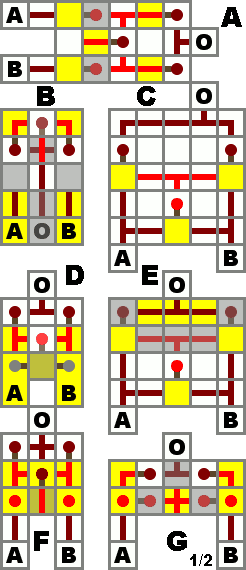
XOR gate designs (click to see it animated).
XOR is a device which activates when the inputs are not the same, when only one is on. XOR is pronounced "exor," and is a shortening of "exclusive or," because it's OR excluding when both inputs are true. The output will turn when exactly 1 of the inputs is on. Adding a NOT gate to the end will produce an XNOR gate, which activates when the inputs are equal to each other. A useful attribute is that an XOR or XNOR gate will always change its output when one of its inputs changes, allowing for 2 switches to be combined to open or close a door, or activate another device.
Design D is not useful unless you want the levers to be fixed to the circuit. Design F is the most widely used.
When using Design F it should be noted that a solid block must be placed over each of the two redstone torches that are not attached to the side of a block, as shown in the diagram at right.
| A | B | A⊻B |
|---|---|---|
| 1 | 1 | 0 |
| 1 | 0 | 1 |
| 0 | 1 | 1 |
| 0 | 0 | 0 |
| Design | A | B | C | D | E | F | G ! |
|---|---|---|---|---|---|---|---|
| Size | 3x5x2 | 3x3x3 | 5x5x1 | 3x3x2 | 5x4x2 | 3x3x3 | 5x2x2 |
| Torches | 5 | 5 | 3 | 3 | 3 | 5 | 8 |
| Redstone | 6 | 5 | 14 | 3 | 12 | 4 | 4 |
| Repeaters | 0 | 0 | 0 | 0 | 0 | 0 | 0 |
| Speed (ticks) | 3 | 3 | 2 | 2 | 2 | 3 | 3 |
| Output direction | fwd. | rev. | fwd. | fwd. | fwd. | fwd. | fwd. |
| Requires levers? | No | No | No | Yes | No | No | No |
XOR gate Design H
XOR gate Design F
XNOR gate (≡)
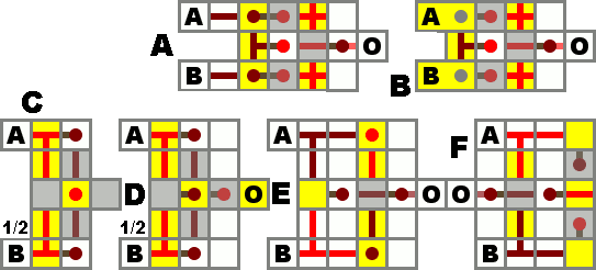
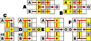
XNOR gate designs (click to see this animated).
In logic, this is more commonly referred to as "if and only if" or "iff" for short. It is a device which activates only when the inputs are equal to each other. In other words when either input changes, the output changes. This is achieved by inverting the output or one input of an XOR. An application of this in Minecraft would be to wire up two levers to the same door.
| A | B | A≡B |
|---|---|---|
| 1 | 1 | 1 |
| 1 | 0 | 0 |
| 0 | 1 | 0 |
| 0 | 0 | 1 |
| Design | A | B | C | D | E | F |
|---|---|---|---|---|---|---|
| Size | 4x3x2 | 4x3x2 | 2x5x4 | 3x5x3 | 4x5x2 | 4x5x2 |
| Torches | 6 | 4 | 4 | 4 | 4 | 4 |
| Redstone | 5 | 5 | 7 | 7 | 10 | 9 |
| Speed (ticks) | 3 | 2 | 2 | 2 | 2 | 2 |
| Output direction | fwd. | fwd. | fwd. | fwd. | fwd. | rev. |
| Levers required? | No | Yes | No | No | No | No |
IMPLIES gate (→)
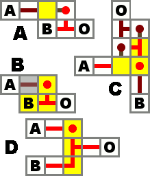
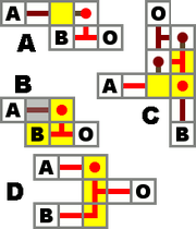
IMPLIES gate.
A device which represents material implication. Returns false only if the implication A → B is false. That is, if the antecedent A is true, but the consequent B is false. It is often read "if A then B." It is the logical equivalent of "B or NOT A".
Design C has a speed of 2 ticks if output is 1, but 1 tick if the output is 0. If you must synchronize the output, consider placing a repeater in front of input A with a 1 tick delay.
| A | B | A→B |
|---|---|---|
| 1 | 1 | 1 |
| 1 | 0 | 0 |
| 0 | 1 | 1 |
| 0 | 0 | 1 |
| Design | A | B | C | D |
|---|---|---|---|---|
| Size | 2x2x1 | 2x1x2 | 2x3x2 | 1x3x2 |
| Torches | 1 | 1 | 3 | 1 |
| Redstone | 1 | 1 | 2 | 2 |
| Speed (ticks) | 1 | 1 | 2 | 1 |
| Inputs isolated? | Only A | Only A | Yes | Only A |
| Output isolated? | No | No | Yes | No |
Latches and flip-flops
Latches and flip-flops are effectively 1-bit memory cells. They allow circuits to store data and deliver it at a later time, rather than acting only on the inputs at the time they are given. Functions using these components can be built to give different outputs in subsequent executions even if the inputs don't change, and so circuits using them are referred to as "sequential logic". They allow for the design of counters, long-term clocks, and complex memory systems, which cannot be created with combinational logic gates alone.
The common feature at the heart of every redstone latch or flip-flop is the RS NOR latch, built from two NOR gates whose inputs and outputs are connected in a loop (see below). The basic NOR latch's symmetry makes the choice of which state represents 'set' an arbitrary decision, at least until additional logic is attached to form more complex devices. Latches usually have two inputs, a 'set' input and a 'reset' input, used to control the value that is stored, while flip-flops tend to wrap additional logic around a latch to make it behave in different ways.
RS NOR latch and Input Stabilizers
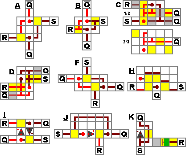
RS NOR latch designs.
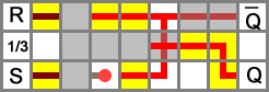
RS NOR latch E design.
Design H, a compact vertical RS NOR latch (Source)
.JPG)
RS NOR Latch Variation using a repeater
A device where Q will stay on forever after input is received by S. Q can be turned off again by a signal received by R.
This is probably the smallest memory device that is possible to make in Minecraft. Note that Q means the opposite of Q, e.g. when Q is on, Q is off and vice-versa. This means that in certain cases, you can get rid of a NOT gate by simply picking the Q output instead of putting a NOT gate after the Q output.
A very basic example of use would be making an alarm system in which a warning light would stay turned on after a pressure plate is pressed, until a reset button is hit.
In the truth table, S=1, R=1 is often referred to as forbidden, because it breaks the inverse relationship between Q and Q. Also, some designs where the input is not isolated from the output, such as B and D, will actually result in Q and Q both apparently being 1 in this case. As soon as either S or R becomes 0, the output will be correct again. However, if S and R both become 0 on exactly the same tick, the resulting state could be either Q or Q, depending on quirks of game mechanics. In practice, this input state should be avoided because its output is undefined. In design E, S=1 and R=1 results in both Q=0 and Q=0.
An example of a RS-NOR latch using a Sticky Piston.
Along with traditional redstone designs, a RS-NOR latch can also be achieved with a Sticky Piston. If a repeater is connected into itself, and given power, the power is maintained until the circuit is disconnected. If a Sticky Piston is positioned with a block to cut off power, it can be connected to the R input and reset it. This method is much simpler than traditional redstone designs, but takes up somewhat more space.
| S | R | Q | Q |
|---|---|---|---|
| 1 | 1 | Undefined | Undefined |
| 1 | 0 | 1 | 0 |
| 0 | 1 | 0 | 1 |
| 0 | 0 | Keep state | Keep state |
| Design | A | B | C | D | E | F | G | H |
|---|---|---|---|---|---|---|---|---|
| Size | 3x3x1 | 2x3x2 | 3x3x3 | 4x2x2 | 7x3x3 | 4x2x1 | 3x2x2 | 1x3x3 |
| Torches | 2 | 2 | 2 | 2 | 2 | 2 | 2 | 2 |
| Redstone wire | 4 | 4 | 8 | 6 | 18 | 4 | 3 | 5 |
| Inputs isolated? | Yes | No | Yes | No | Yes | Yes | Yes | No |
| Outputs isolated? | Yes | Yes | No | No | Yes | Yes | Yes | No |
| Input orientation | opposite | opposite | adjacent | either | adjacent | opposite | adjacent | opposite |
Enable/Disable RS NOR latch
This can be made by having AND gates on the inputs, and connecting both AND gates to a third input, E. If E is true, the memory cell works as normal. If E is false, the memory cell will not change state.
Input stabilizing cell
Input Stabilization Circuit
This device will stabilize an input once received even after the input source stops. It is essentially a non-resetable RS-NOR Latch where a repeater powers itself. For example a stone button or pressure plate signal could be turned into a permanent power source with one push.
RS NAND latch
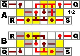
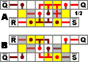
RS NAND latch designs.
Since NOR and NAND are the universal logic gates, a design for an RS NAND latch is just an RS NOR with inverters applied to the inputs and outputs. The RS NAND is logically equivalent to the RS NOR as the same inputs for R and S give the same outputs. This circuit is impractical in Minecraft because a single redstone torch acts as a NOR gate.
When S and R are both off, Q and Q are on. When S is on, but R is off, Q will be on. When R is on, but S is off, Q will be on. When S and R are both on, it does not change Q and Q. They will be the same as they were before S and R were both turned on.
| S | R | Q | Q |
|---|---|---|---|
| 1 | 1 | Keep state | Keep state |
| 1 | 0 | 0 | 1 |
| 0 | 1 | 1 | 0 |
| 0 | 0 | Undefined | Undefined |
| Design | A | B |
|---|---|---|
| Size | 6x3x3 | 6x3x2 |
| Torches | 6 | 6 |
| Redstone | 10 | 8 |
| Input orientation | adjacent | opposite |
D Flip-Flop & Gated D Latch
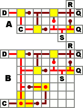
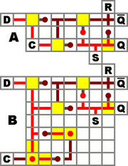
A gated D latch and D flip-flop
A D flip-flop, or "data" flip-flop, sets the output to D only when its clock input transitions from OFF to ON (positive edge) or ON to OFF (negative edge). A flip flop is said to be an edge triggered device, while a gated latch is a level triggered device (triggered on either an OFF or ON clock/enable input). The basic level-triggering gated D latch (design A) sets the output to D as long as the clock is set to OFF, and ignores changes in D as long as the clock is ON.
You can often turn a gated D latch into a D flip flop by including an edge trigger. Design B includes a positive edge trigger and it will set the output to D only when the clock goes from OFF to ON.
In these designs, the output is not isolated; this allows for asynchronous R and S inputs (which override the clock and force a certain output state). To get an isolated output, instead of using Q simply connect an inverter to Q.
Side view of a vertical D latch, design C (Source)
Design C is a one block wide version of A, except for using a non-inverted clock. It sets the output to D as long as the clock is ON (turning the torch off). This design can be repeated in parallel every other block, giving it a much smaller footprint, equal to the minimum spacing of parallel data lines (when not using a "cable"). A clock signal can be distributed to all of them with a wire running perpendicularly under the data lines, allowing multiple flip-flops to share a single edge-trigger if desired. The output Q is most easily accessed in the reverse direction, toward the source of input. Q can be inverted or repeated to isolate the latch's Set line (the unisolated Q and Q wires can do double duty as R and S inputs, as in design A).
Design D (Source)
Design E is a more compact version of design A.
Design E provides a more compact version of A, while still affording the same ceiling requirement. The design to the right in the image however requires 1 more block ceiling allowance, but allows the edge trigger to act on a high input. This additional ceiling requirement can be circumvented by simply moving the vertical NOT gate, to a lateral position 2 blocks downward. There is also the option of simply providing a NOT gate on the clock for your data bank, thus preventing the requirement of a gate for each flip flop.
Design F
Design F holds its state while the clock is high, and switches to D when the clock falls low. Note the presence of blocks above the top wire to cut connections. These are indicated by yellow hashing on the image. The repeater serves to synchronise the signals that switch out the loop and switch in D. It must be set to 1 to match the effect of the torch.
Gated D Latch - Design G
Design G is designed to be built into walls. If you want to switch the state the lever must be flipped before you press the button, this works both ways. The circuit is one wide and somewhat small. Also it takes about 1 tick less time than the traditional 1 wide (Design C)
| Design | A | B | C | D | E | F | G |
|---|---|---|---|---|---|---|---|
| Size | 7x3x2 | 7x7x2 | 1x5x6 | 2x4x5 | 3x2x7 | 3x2x6 | 1x5x6 |
| Torches | 4 | 8 | 5 | 8 | 5 | 4 | 6 |
| Redstone wire | 11 | 18 | 5 | 5 | 13 | 8 | 6 |
| Repeaters | 1 | ||||||
| Trigger | Level | Edge | Level | Level | Level | Level | Level |
| Output isolated? | No | No | No | No | No | Yes | No |
| Input isolated? | Yes | Yes | C Only | Yes | Yes | No | C Only |
JK Flip-Flop & Latch
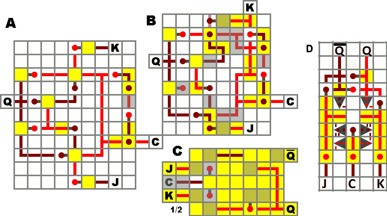
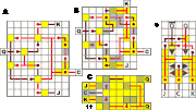
JK flip-flop designs.
A JK flip-flop is another memory element which, like the D flip-flop, will only change its output state only when the clock signal C changes from 0 to 1 xor 1 to 0 (edge-triggered, design A and B), or while it holds a certain value (level-triggered latch, design C). When the flip-flop is triggered, if the input J = 1 and the input K = 0, the output Q = 1. When J = 0 and K = 1, the output Q = 0. If both J and K are 0, then the JK flip-flop maintains its previous state. If both are 1, the output will complement itself — i.e., if Q = 1 before the clock trigger, Q = 0 afterwards. The below table summarizes these states — note that Q(t) is the new state after the trigger, while Q(t-1) represents the state before the trigger.
The JK flip-flop's complement function (when J and K are 1) is only meaningful with edge-triggered JK flip-flops, as it's an instantaneous trigger condition. With level-triggered flip-flops (e.g. design C), maintaining the clock signal at 1 for too long causes a race condition on the output. Although this race condition is not fast enough to cause the torches to burn out, it makes the complement function unreliable for level-triggered flip-flops.
| J | K | Q(t) |
|---|---|---|
| 0 | 0 | Q(t-1) |
| 0 | 1 | 0 |
| 1 | 0 | 1 |
| 1 | 1 | Q(t-1) |
| Design | A | B | C | D |
|---|---|---|---|---|
| Size | 11x9x2 | 9x8x2 | 5x7x4 | 5x7x2 |
| Torches | 12 | 12 | 11 | 7 |
| Redstone | 34 | 35 | 22 | 20 |
| Repeaters | 0 | 0 | 0 | 6 |
| Accessible Q? | No | No | Yes | Yes |
| Trigger | Edge | Edge | Level | Edge |
Vertical JK Flip-Flop 15Wx10Hx1D
This is a vertical JK Flip-Flop from the basis of design A. This circuit can be built together in series side-by-side by spacing the circuit one block apart and alternating the direction of the circuit (left-to-right, right-to-left, etc.). By adding an AND gate combining K and Q at the end of this circuit and outputting the result into the inputs J and K of the next gate you can get a binary counter. For optimal space saving you can pass input K through the block it hits by replacing the redstone wire with a relay. Then you can just add additional redstone wire on the other side to bring the input of K over to Q. There is also enough space to begin a vertical AND gate to where the result is just to the right of output Q.
NOTE: Although not marked on the page, all relays should be set to their first notch EXCEPT ONE. Starting from input K move 8 blocks over and 2 up. That gate needs to have the longest delay at 4 notches. Also, all gates will finalize at the same time when synced to the same clock. A clock speed of 1.5 seconds (4 relays in a loop) has proven to be the most effective on a multiplayer server; although the relays can freeze when warping or leaving the area.
T Flip-Flop
T flip-flops are also known as "toggles." Whenever T changes from OFF to ON, the output will toggle its state. A useful way to use T flip-flops in Minecraft could for example be a button connected to the input. When you press the button the output toggles (a door opens or closes), and does not toggle back when the button pops out. (Designs C and D do not have an incorporated edge trigger and will toggle multiple times unless the input is passed through one first.) It is also the core of all binary counters and clocks, as it functions as a "period doubler", turning two input pulses into one output pulse.
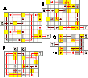
T flip-flop designs.
Design A has a large footprint, but is easy to build. It (and B, which is a slightly compacted version of A) is essentially a JK flip-flop with the inputs for J and K removed so that it relies on the edge trigger (right side of the diagram) to keep it in the stable state and only allow a single operation per input.
Design C has a smaller footprint and an easily accessible inverse output, but lacks an edge trigger. If the input is kept high, it will repeatedly toggle on and off, cycling quickly enough to burn out its torches. For example, if the button mentioned above is wired directly to its input, the device can toggle several times before the button shuts off. Even a 4-clock is too slow to reliably result in only one toggle. Adding an edge trigger by routing input through a separate pulse generator (design B' seems to work best) will prevent this problem, as will any other means of sending it a short (2-3 tick) pulse of power.
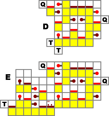

Side view of vertical T flip-flop designs.
Designs D and E are much taller than the others, but only a single block wide, making them good for situations where floorspace is limited. D is level-triggered like design C, which can save space when distributing one input pulse to multiple flip-flops. Design E has an edge trigger.
The edge trigger makes the unit insensitive to the duration of the input pulse, thus it's easy to daisy-chain multiple units to create a binary counters or period-doublers for slow clocks.
These designs are based on the vertical gated D latch (design C) with the inverse output looped back to the input.
T flip-flop designs H and J.
Design H uses timing; the repeaters exactly match the torches. The core of the design is a loop with two torches that acts as the memory cell. When the input is received, it temporarily substitutes in a loop with only one redstone torch - a not gate. This flips the input. The input must be held high and driven low with an edge. A suitable circuit is simply a torch and a repeater set on 4 in parallel. Without this, it will oscillate and burn out the torches, so lay the circuitry to hold the input high before putting in the loops. In addition to being small, the design is fast - the output flips almost as soon as the input goes low. It seems to be the smallest now if we do not include an edge detector on the input (the suggested edge detector is 3x4x1). Note that three blocks are needed above the redstone to stop cross-connections. In the diagram, these are shown with gray squares. You can put a fourth one in over the repeater for symmetry if you wish. These blocks do not add to the height of the unit, rather, they are at the same layer as the two upright torches.
Design I does not use repeaters. The input is the Down block, the output can be the top left corner torch.
The Output blinks when toggled.
Layout of the I T Flip-Flop.
Design J is the smallest design of T Flip-Flop on this page. It is a compact version of the H design and has an edge trigger. Depending on a combination of game mode (SMP or single player), orientation, and game version, the repeater delay may need to be adjusted to eliminate output flickers on state changes. In some situations, it will not work at all unless the repeater delays are adjusted. It has been reported that for proper operation in some cases, the repeaters have needed to be set to 2-1-4 or even 4-2-4.
A demo of this flip-flop working correctly can be downloaded at [1]. It is a zipped world from a local installation of the minecraft server (v1.6.6).
T flip-flop designs Z1 to Z3
With Beta 1.7.3 operation of the Sticky Pistons was changed. If a sticky piston is activated with a one-pulse, it will push or pull a block, but not push and pull it back. This makes it easy to build compact T flip-flops. Z1 is the design with the smallest footprint (sticky piston and movable block are on level 2 above the torches), Z2 is the lowest one - only one block height, Z3 is a vertical design. All include the necessary edge trigger. But keep in mind that it is currently not clear whether this behaviour of the sticky pistons is considered a bug or not.
With the release of 1.0 a placed lone redstone dust was changed from sending power in all horizontal directions (a cross shape) to sending power in no direction (a dot shape). (Note: this is not entirely factual, the shape of redstone has changed, but it's operation is intact, see this image. There were, however, changes to how redstone connects to repeaters, making designs Z1 and Z2 have problems). This means that the block meant to recieve two inverted inputs in the edge trigger designs of Z1 and Z2 only recieves power from the inverted input (the one with a torch), and not the repeated input.
The problem with the Z1 design can be fixed by placing a block at the output of the repeater, then place redstone dust on top of that block and the adjacent block.
Z1 Fixed for 1.0
The problem can be circumvented in design Z2 by placing redstone dust on the block meant to recieve power (the topmost block in the picture). Also, place a block above the redstone dust coming from the torch to isolate the wires. This will make the wire coming from the torch go into the block, and the wire from the repeater go on top of the block. With the same solution in design Z1 the dust on top of the block would power the sticky piston while the torch was off, meaning the sticky piston would always be extended.
NOTE: Some of the illustrated T Flip-Flops to the right don't include the typical Q outputs. If you want to use the Q then just add an inverter to Q.
NOTE: Using design E you may require a delay in the connection between the edge trigger and flip-flop in order to maintain a high input long enough to toggle the flip-flop
| Design | A | B | C | D | E | H | I | J | Z1 | Z2 | Z3 | ||
|---|---|---|---|---|---|---|---|---|---|---|---|---|---|
| Size | 7x9x2 | 7x8x2 | 5x6x3 | 1x7x6 | 1x12x7 | 3x7x2 | 6x5x2 | 3x7x2 | (3x4x2) | (3x7x1) | (1x6x4) | ||
| Torches | 10 | 10 | 8 | 7 | 12 | 4 | 5 | 5 | (3) | (3) | (3) | ||
| Redstone | 28 | 29 | 22 | 9 | 14 | 12 | 18 | 10 | (4) | 5 | (4) | ||
| Repeaters | 0 | 0 | 0 | 0 | 1 | 2 | 0 | 3 | 1 | 2 | 2 | ||
| Sticky Pistons | 0 | 0 | 0 | 0 | 0 | 0 | 0 | 0 | 1 | 1 | 1 | ||
| Accessible Q? | No | No | Yes | No | No | Yes | No | Yes | No | No | No | ||
| Trigger | Edge | Edge | Level | Level | Edge | Level | Level | Edge | Edge | Edge | Edge |
Other redstone components
see Piston circuits
Repeater/Diode
.gif)
Redstone Repeater Block
- See the Redstone Repeater article for full details.
As of Minecraft Beta version 1.3, a Redstone Repeater block can be crafted from 3 stone, two redstone torches and one redstone dust. It can be used to compactly extend the running length of a wire beyond 15 blocks, or apply a configurable delay of between 1 to 3 ticks 4 ticks.
Traditional repeater/diode
Example of a Traditional Repeater
Using two Redstone torches in series can effectively extend your running wire length past the 15-block limitation. As of 1.0.2 (the July 6th 2010 update), there must be a strip of wire between the two Redstone torches. Repeaters make it possible to send long-distance signals around the map, but in the process, slow down the speed of transfer. To reduce delays, you can stretch out the repeater so that some areas of the wire are consistently in the opposite state, but as long as the number of Redstone torches, or, effectively, NOT Gates is even, the signal will be correct. In more advanced circuits, repeaters can be used as a semi-conductors to isolate inputs or outputs.
Rail T flip-flop
Rail T flip-flop
Another rail T flip-flop design
The Rail T flip-flop is a T flip-flop which uses rails and redstone. It is slower than traditional redstone-only circuits, but takes up less space[citation needed] than a normal T flip-flop and allows for easy access to the input and output.[citation needed]
The wooden squares at the rail corners are pressure plates that will switch the conventional RS-NOR latch at the bottom.
Two-way repeater
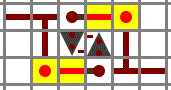
Two way repeater
Using repeater blocks
This circuit acts as a two-way repeater, essentially serving as an elongated strip of redstone. Unlike normal repeaters, which only work in one direction, this circuit allows a signal to be sent through it from either side. It does not have a traditional input or output, but rather two spots which serve as both input and output, depending on what is attached to them. Whenever either one of them is receiving power, the other one is also receiving power. Whenever one of them is off, both are off.
Also, this circuit even tells you the direction the signal is flowing. Of the two torches which appear unlit in the diagram, whenever the circuit is powered, one will be lit. It will be the only lit torch in the circuit, and it will face the direction the power is moving. Thus, if there is an input from A, the bottom-right torch will be lit. In short, the primary purpose of this circuit is to simulate the function of redstone wire without restricting signal direction like a repeater, but it also happens to indicate which direction the signal is flowing.
This circuit can be made three blocks shorter using repeater blocks to prevent short-circuiting.
The north/south quirk
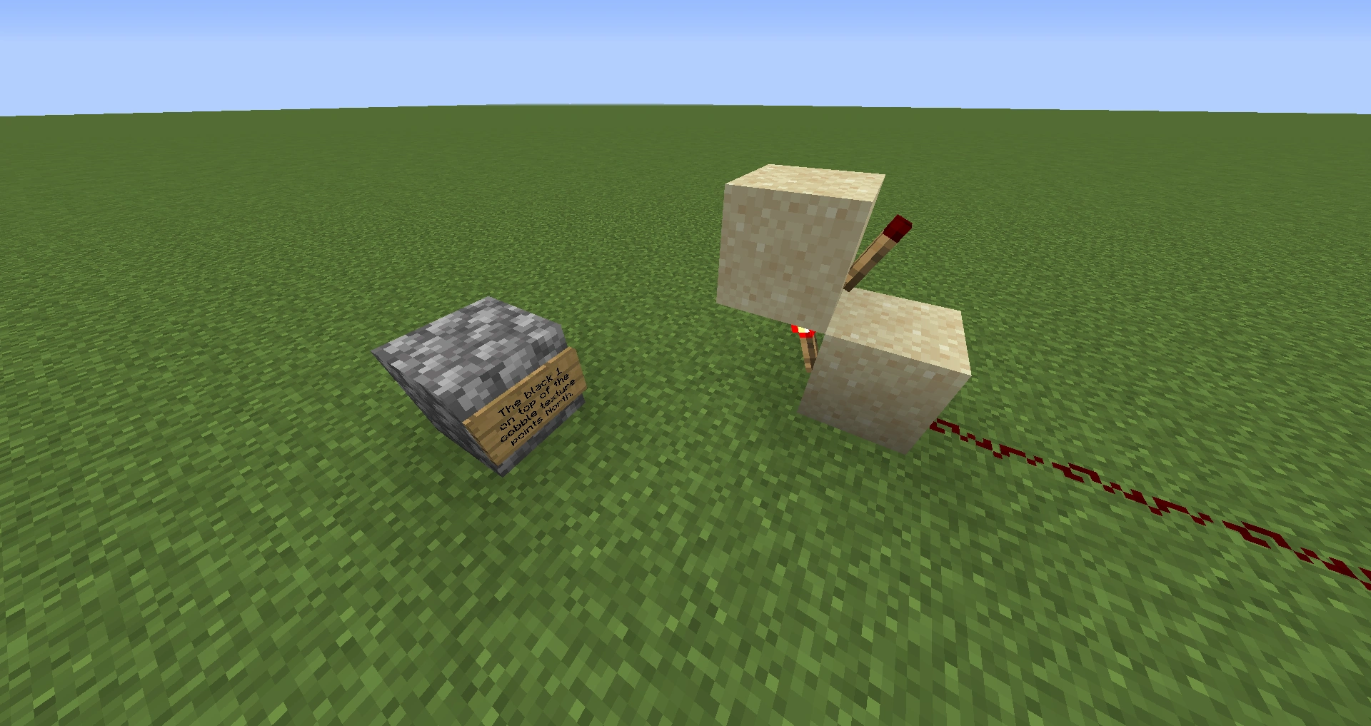
Fig. 1 - The two possible orientations.
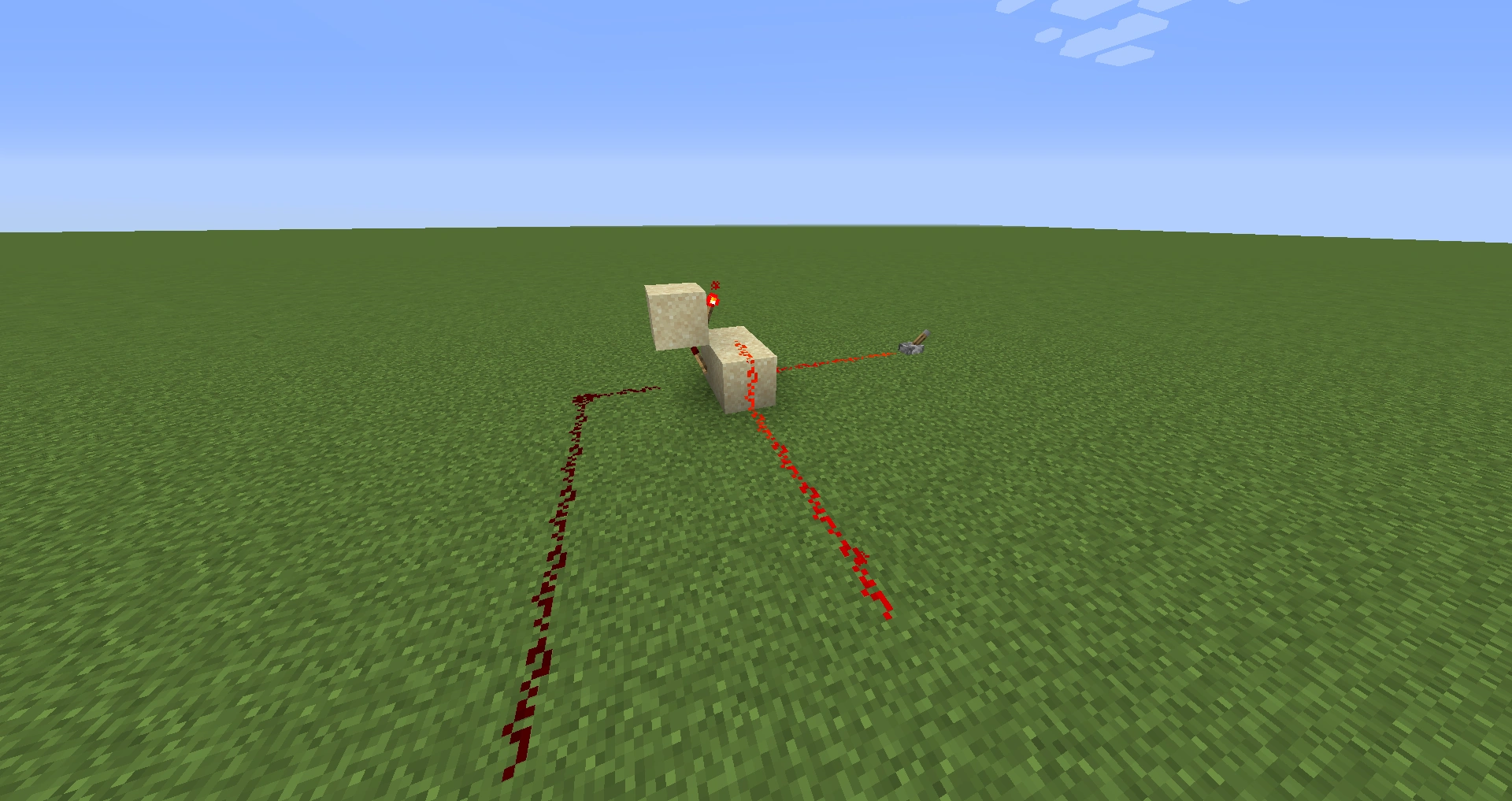
Fig. 2 - Equal-delay inverse outputs.
A specific arrangement of torches which would normally be expected to behave identically to a traditional 2-torch repeater, causing a 2-tick delay in signal transmission, instead causes only a 1-tick delay. (See figure 1.) When constructed with the torches facing east and west, this arrangement causes the expected 2-tick delay, but when facing north and south, the second (top) torch changes state at the same time as the first, after only a single tick.
The quirk can cause unexpected bugs in complicated circuit designs when not accounted for, but it does have several practical uses. For example, double doors require opposite power states, but inverting one signal delays that door's response by 1 tick. Prior to Beta 1.3 and the introduction of the Redstone Repeater, the only known way to perfectly synchronize them was with this 1-tick repeater. Another application is in creating a clock circuit (see below) with an even pulse width and period.
Finally, as a generalization of the double-door use, the North/South Quirk can be used to obtain two signals which are always inversely related without the additional 1-tick delay a NOT gate normally causes in the second signal. (See figure 2.) This can be especially useful in circuits where precise timing is important, such as signal processing that relies on the transition of an input from high to low and low to high (on to off and back), for example by sending each of the inverse signals through separate edge detectors (see pulse generators below) and then ORing their outputs.
Delay circuit
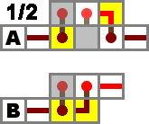
Compact delay circuits used to increase signal travel time.
Sometimes it is desirable to induce a delay in your redstone circuitry. Delay circuits are the traditional way to achieve this goal in a compact manner. However, in Beta 1.3 the single-block Redstone Repeater was introduced, which can be set to a 1, 2, 3 or 4 torch delay, effectively rendering these delay circuits obsolete. The historical circuits are shown here for completeness, and will still work should you choose to build one.
These two delay circuits utilize torches heavily in favor of compactness, but in doing so the builder must be aware of the North/South Quirk. For maximum signal delay, construct these designs so that the stacked torches face east and west. For a fine-tuned delay, adjust the design to rotate one of the alternating-torch stacks to face north and south, or add an additional stack in that orientation.
Design A gives a 4 tick delay, while design B gives a 3 tick delay.
Clock generators
Clock generators and pulsars.
Clock generators are devices where the output is toggling on/off constantly. The simplest stable clock generator is the 5-clock (designs B and C). Using this method, 1-clocks and 3-clocks are possible to make but they will "burn out" because of their speed, which makes them unstable. Redundancy can be used to maintain a 1-clock, even as the torches burn out; the result is the so-called "Rapid Pulsar" (designs A and F). Slower clocks are made by making the chain of inverters longer (designs B' and C' show how such an extension process can be achieved). or, you could just use a repeater set to 3 or 4.
Using a different method, a 4-clock can be made (design D). A 4-clock is the fastest clock which will not overload the torches.
A 4-clock with a regular on/off pulse width is also possible as seen in design E. This design uses five torches, but can be constructed so that it has a pulse width of 4 ticks by employing the North/South Quirk. It is important that the orientation of this design (or at least the portion containing the stacked torches) be along the north/south axis.
The customary name x-clock is derived from half of the period length, which is also usually the pulse width. For example, design B (a 5-clock) will produce the sequence ...11111000001111100000... on the output.
Designs F and G are examples of possible vertical configurations.
Design H is a stable 1-tick piston clock from the user BlubQ. To activate this clock: Build it as shown in the image but place the block in front of the piston as the last block. The piston should now extend and retract quickly.
You won't be able to see the redstonedust turning on and off because it's faster than the game updates itself.
There is still a signal at the output of the clock. To check if its working correctly place a piston at the output wire. It should extend/retract fast.
Repeater clocks
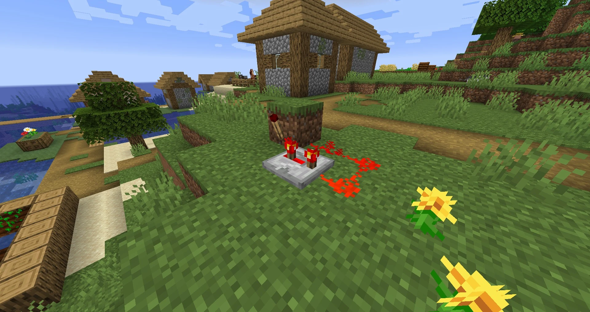

Variable clock generator using redstone repeaters. The delay can be increased almost infinitely with more repeaters.
1 tick clock (manually started)
With the addition of Redstone Repeaters in the Beta 1.3 update, clock generators can be simplified to at most one block, one redstone torch and from one to any number of repeaters chained together or just two (or more) repeaters and four redstone dust.
Very rapid clocks with even pulsewidth can be designed out of only Redstone Repeaters. By increasing the delay on each repeater or by increasing the number of repeaters in the loop, the clock can be slowed. These clocks act as variable clocks, but have higher maximum speeds, but these can't be used as it soon burns out the torch, you have to set the repeater on its third setting to stop it burning out.
Piston clocks
Example of a piston clock.
After their addition in Beta 1.7, Pistons can be used to create new types of clocks with a modifiable pulse delay without the use of pulse generators. This allows other pistons to be clocked in a fashion that only leaves the arm extended for the time required to push an adjacent block, which in turn facilitates the creation of more complex and faster piston contraptions.
Minecart clocks
A basic Minecart Clock
Minecart clocks are simple, easy to build and modify, but are somewhat unreliable. Minecart clocks are made by creating a small circular track of minecart rails with one or more minecart booster and detector rail, and running an empty minecart through the loop. The cart is propelled endlessly by the boosters and generates a redstone signal as it passes over the detector rail. Minecart Clocks are, unlike piston clocks, completely silent, and can be extended or shortened easily by adding and removing track to adjust the delay between signals. Perhaps the biggest disadvantage to using a minecart clock is the fact that it is easily disrupted by the player or mobs, or the fact that it requires more space to be constructed in. Finally, the necessity of gold in the construction of the booster rails may be a limiting factor to players without access to it.
Half-Day minecart clock
An example of a multistage Half-Day clock, note the wiring to the right of the red line is only needed if you are hooking it up to a sequence of RS-latches to control a clock face
An advanced Rail T Flip-Flop is a critical component in the Half-Day Clock. As it relies on the item decay code to send power to booster rails and trigger two separate mine-cart pressure plates. The Half-Day timer always toggles state after 5 minutes even with large amounts of lag, making it the most accurate clock currently in Minecraft.
Controllable clocks
Controllable clocks are a combination of a 5 Clock and a AND or a NAND gate. The output ends at the first inverter of the clock, and one of the AND inputs is the output of the 5th inverter of the clock.
Toggleable clock
A button based toggleable clock
By adding an inverter instead of a repeater at any point in an average clock and wiring a lever to the main block of this inverter, a clock that can be toggled on and off can be created. It is important to either use 3 or more repeaters (or delay if less are used), as it seems to burn out otherwise.
It is also possible to create a compact toggleable clock by means of a button (or other redstone pulse) using 2 modified pulse limiters (as shown below) in series. You may have to modify the repeater(s) in the first pulse limiter to give more delay and therefor a longer pulse, and more reliable shut-off.
Blink device
Random short generator

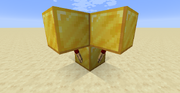
Blink device
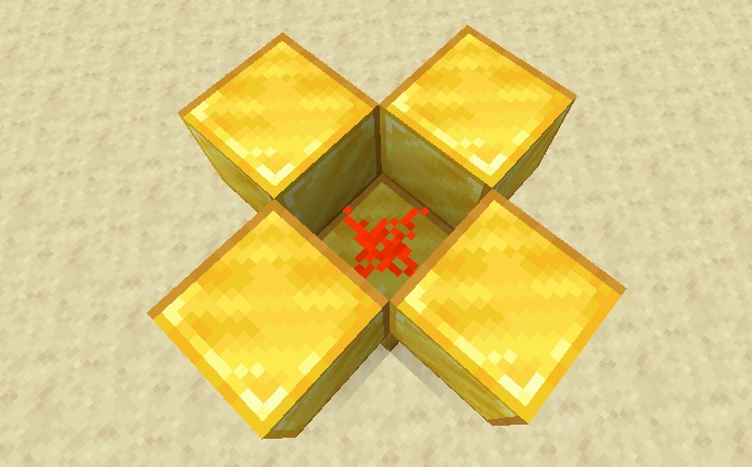
Blink device on inside
This device creates energy in an irregular sequence. It is a variant of the "Rapid Pulsar" design shown above, except that each torch pulses in an irregular pseudo-random pattern as each torch coming on turns the other three (and itself) off, and occasionally burning out before being reset by a block update after several seconds, during which time other torches blink.
You can build this device by placing a block with one redstone torch on every side. Place some redstone on top of the block, place a new block on top of each torch, and then wire it up to different circuits.
Extreme Delay Circuits
By utilizing two racetracks of repeaters with different delay lengths and an AND gate, one can generate extremely long delays from an input signal to an output signal with remarkably compact design and low resource cost.[1]
Because both race tracks need to line up to both trigger the AND gate and having different periods (e.g. 55 ticks and 56 ticks, using 28 repeaters) the actual delay between input and output increases dramatically (e.g. 3080 ticks, or just over 5 minutes, compared to the 112 ticks using the same number of repeaters in a line).
ABBA Switch
ABBA switch.
Many piston creations require them to fire sequentially in one order, and close in the opposite. Such as in secret piston doors, and the circuits for them can often be huge. ABBA switch is named so as the compact circuit is designed to open output A, then B. Then close output B, then A.
ABBA switch.
Lengthened ABBA switches.
The switch can also be extended to add outputs C, D, and so on. However doing so lengthens the circuit time that much more, as power must reach the opposite end of the ABBA Switch before any output reaction takes place. The settings of the repeaters can also be increased, purposely increasing the timing of any length of switch.
Pulse generators
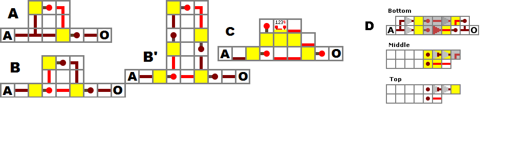
Pulse generator designs.
A pulse generator is a device that creates a pulsed output when the input changes. A pulse generator is required to clock flip-flops without a built-in edge trigger if the clock signal will be active for more than a moment (i.e., excluding Stone Buttons).
Design A will create a short pulse when the input turns off. By inverting the input as shown in B, the output will pulse when the input turns on. The length of the pulse can be increased with extra inverters, shown in B'. This is an integral part of a T flip-flop, as it prevents the flip-flop changing more than once in a single operation. Designs A and B can be put together to represent both the increase of A and the decrease of A as separate outputs, these can then be read to show when the input changes, regardless of its state. Redstone Repeaters can be used to change the length of the pulse, by placing one or more in series in the delay circuit between the two redstone torches (referring to design A). NOTE: This design no longer works with the 1.6 update. In order for any pulse to be sent through, there must be at least one more torch of delay between the first off state and the second. Adding a repeater on the first setting will add the minimum one additional torch of delay without breaking the pulse generator.
A pulse generator which causes a short pulse of low power instead of high can be made by removing the final inverter in design B' and replacing it with a wire connection. This is the type used in designs A and B of the T and JK flip-flops (when J=1 and K=1) to briefly place these devices in the 'toggle' state, long enough for a single operation to take place.
- These circuits seem to burn themselves out in single player and (apparently) in SMP after the 1.6 update.
Type D is unique in design. Due to its nature, there is no way to correctly build it. This is because there are multiple input and output locations you can specify to fit your needs. It uses only 4 components: redstone wire, a sticky piston, a solid block (e.g. dirt or stone), and an input.
Piston pulse design.
This design creates a faster tick rate than a redstone torch. Note that you will be able to use the 1st notch (Only on multiplayer please verify. Single player 1-tick design here) on the diode to create and very quick pulse since there isn't a redstone component to burn out. Due note, that the obsidian in the design pictured prevents this design from working, but was done for ease of creating the image.
Pulse limiters
Pulse limiter
Pulse limiter
A pulse limiter limits the length of a pulse. It is useful in sequential bit activation to prevent multiple bits from being activated by the same pulse. The construction expects a default "on" input (left) and by default gives an "on" output (right).
When the limiter receives an off input, it generates a pulse with a length equal to the delay of the right repeater plus the delay of the torch minus the left repeater (make sure that this yields a positive value) or the length of the initial pulse, whichever is shorter. For example: in the picture, the pulse is calculated as .1 + .1 - .1 = .1 or one tick, assuming the activation pulse is >= 1 tick. Be aware of the North/South quirk, as this can affect the delay of the torch. When the input is turned back on, the limiter will not emit a second pulse.
Another pulse limiter design can be seen on the left. The repeater in the center must be set to at least a 3 click delay, or the signal will not be sent.
Piston pulse limiter
Piston limiter
Another solution for having a short pulse is using pistons instead of torches. the button will be spit up in two lines. one lines is delayed by a repeater. this repeater can be tuned in order to get the pulse length that's desired. The piston will be activated and blocking the second line.
Pulse sustainer
Pulse Sustain Circuit (large)
Compact Pulse Sustainer Circuit
Please refer to the Monostable circuit section.
A pulse sustainer is used to lengthen the duration of a pulse type input (such as a button or pressure plate). Essentially the pulse input opens a constant power source (redstone torch) via a piston switch (piston 1). After the signal is delayed by the redstone repeaters, the circuit is closed once again via piston 2. The output signal can be taken from anywhere along the redstone repeater circuit segment, as shown.
Monostable circuit
Monostable Circuit (large)
A device that turns itself off a short time after it has been activated. Basically, it consists of a RSNOR-latch and delay hooked up to its reset. The trigger input activates the latch's SET input, and after a delay set by the repeaters, the RESET activates, turning the output off again. The delay (e.g. the length that the output is high) can be set to any value by adding repeaters into the chain.
As a pulse will often have a shorter duration as it passes through complex circuitry, monostable circuits are useful for relengthening the duration, as the output always lasts the same amount of time, regardless of input duration.
It can also be used to delay a signal by using its reset signal as output.
A more compact version fits into a (3x3x2). Very short pulse and repeater has to be set to one of the last two settings in order to work. Repeaters can be added to lengthen pulse.
(Compact) Monostable Circuit. The length of the pulse is one tick less than repeater setting.
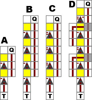
Monostable Circuit/Pulse Lengthener (long)
Alternatively, a (1x7x2) vertical device can be built to fit neatly against/into a wall. As in the other cases, the length of time that the output is high can be adjusted by adding or removing repeaters. (N.B. the repeaters should be flat on the floor, in the positions shown). This design lacks the RSNOR-latch of other designs and will only be useful in constant-input circuits. For momentary circuits, this design will not lengthen an input signal like the other designs, just cut the signal early.
Monostable Circuit (vertical)
A compact yet simple 2-X-1 device can also be built if you're constricted to long hallways with little room for width. However, due to the design, this only works with pulsed inputs and not with constant-input circuits. Unlike the previous designs, however, it can deal with 1-tick pulses. Design A shows the basic device that lengthens the incoming pulse by 1. Design B shows how you can expand this to lengthen the pulse by 3. Design C, which lengthens incoming pulses by 6, shows how you can make the device more compact by lengthening the delay of the repeaters. Unfortunately, this particular design only works properly if the incoming pulse is at least two ticks long. Design D shows how you can skirt around this problem without terribly affecting the compact nature of the device. It lengthens pulses by 7 and works with any length pulse. Note that the number of ticks the device lengthens the pulse by is equal to the sum of the delays on the repeaters in the design, not including the first one.
Vertical transmission
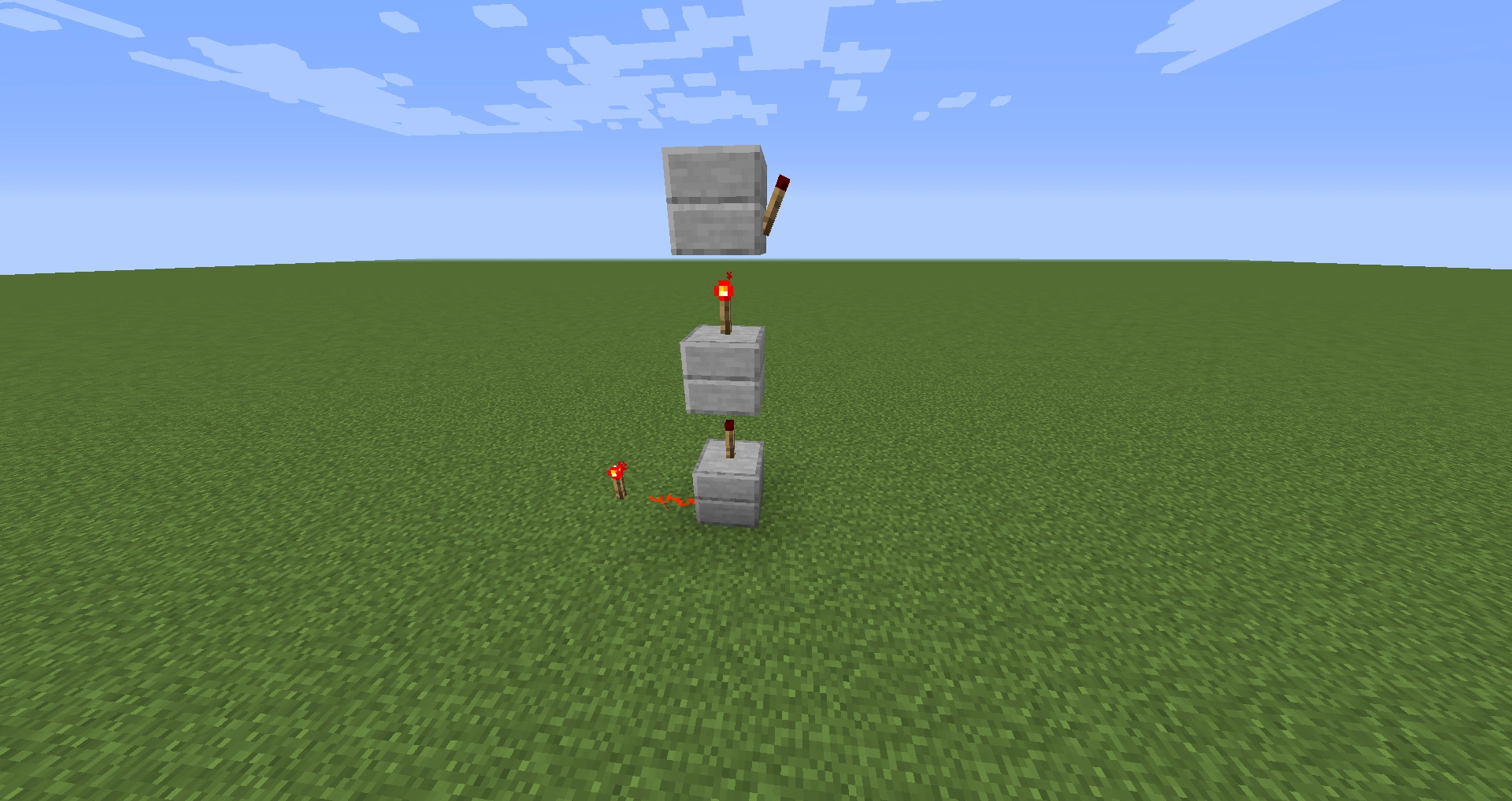
A 1x1 tower of upward repeaters
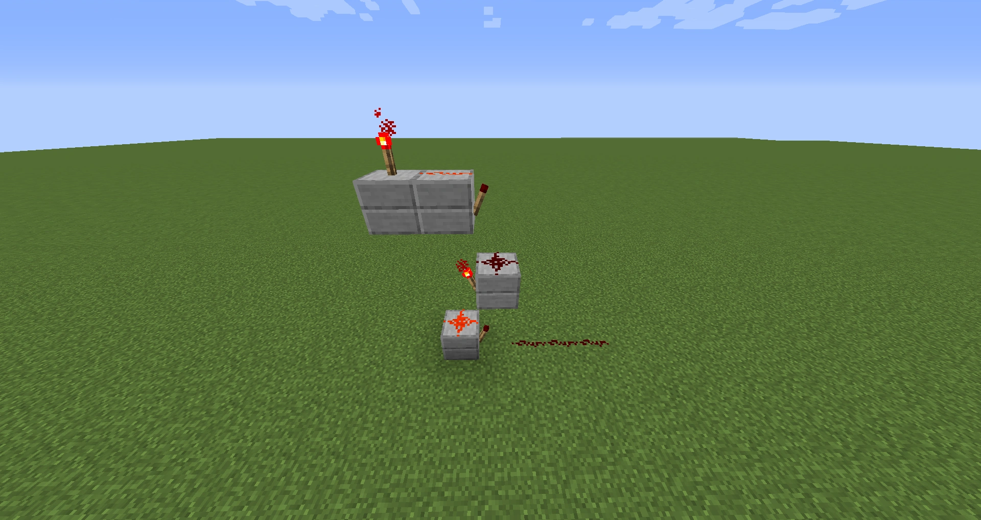
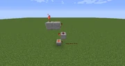
A 1x2 tower of downward repeaters
Sometimes it's necessary or desirable to transmit a redstone state vertically (e.g. to have a central control or status for several circuits from a single observation point.) To transmit a state vertically, a 2x2 spiral of blocks with redstone can be used to transmit power in either direction, and the spiral is internally navigable (i.e. one can climb or descend within the tower).
If repeaters are necessary, there is a 1x1 design for transmitting a state upward, and a 1x2 design for transmitting a state downward. For this to be effective you must not finish the top torch on, only off will switch the current when needed. Internal navigability of these designs inside a 2x2 tower interior can be maintained using ladders.
Multiplexer
Multiplexer (Animated)
A multiplexer (mux) is a device that selects one of two or more inputs and outputs the selected input. This multiplexer can be chained together with itself, allowing for 3 or more bit multiplexing.
Note: The inputs are (NOT A), B, and C.
-Inputs A and B are on the bottom (left=(NOT A), right=B).
-Output is on the top. C (Control) is the uppermost layer of redstone. Any connection to it will work.
Dimensions: 4x3x3
Redstone: 16 (12 wire, 4 torches)
Relay
Large Version: [IMG]http://i1221.photobucket.com/albums/dd478/AJFayer/Relay.jpg[/IMG]
Medium Version: [IMG]http://i1221.photobucket.com/albums/dd478/AJFayer/RelayM.jpg[/IMG]
Small Version:
Relay (small)
Please refer to the Mux (Multiplexor) section. This is a repetition of it and should be ignored.
The relay allows you to have one input be sent to two different outputs that you can switch between. It consists of two AND gates, and an RS NOR latch. The relay defaults to one output, and by setting the latch you can change to the secondary output. Unlike just an RS NOR latch, which outputs a constant signal from one output or the other, the relay allows you to send a non-constant signal, which allows you to send no signal, or to send a signal to either output. It is useful for locks, and other applications where you want a non-constant signal to go one output until a triggering event occurs. Unlike a real world relay, it doesn't require constant power to keep it sending to the secondary output. It also requires power to reset to the primary output.
An example of when you would want a relay. A lock that requires you to push multiple buttons in the correct order. A relay allows you the ability to have one button be used multiple times in the sequence by having the relay send the signal to different parts of the unlocking mechanism at different times. You could also make a multi-digit, binary combination lock that requires multiple numbers to be entered using switches. You can use four switches to enter a four digit number and a fifth switch to check the entered number. The fifth switch can flip relays to all the other switches allowing you to use the same switches to set the second number.
-A relay is built by linking two AND gates with an RS NOR latch sending its two outputs to either AND gate. Then split a single input to the other AND gate inputs. Trigger the latch to change outputs.
Edge detectors
Rising (left) and falling (right) edge detectors.
These devices send a short pulse when they have a rising or falling edge as their input. A rising edge is when a signal changes from low (0) to high (1) and falling is the opposite, high to low.
Reversible Sequence Activator
A reversible sequence activator.
This device will set on the output so that when input S is pressed, output A goes first on, then B. When input R is pressed, output B goes first off, then A effectively inverting the order of operations for uses such as double-piston extenders.
Shift Register
Shift Registers are a cascade of D Flip-Flops, or JK Flip Flops sharing the same clock, which has the output of any one but the last flip-flop connected to the "data" input of the next one in the chain, resulting in a circuit that shifts by one position, when enabled to do so by a transition of the clock input.
Logical Shift Right or Left: In a logical shift, the bits that are shifted out are discarded, and zeros are shifted in (on either end). This inserts bits with value 0 instead of copying in the sign bit. Hence the logical shift is suitable for unsigned binary numbers.
Rotate Shift: Another form of shift is the circular shift or bit rotation. In this operation, the bits are "rotated" as if the left and right ends of the register were joined. The value that is shifted in on the right during a left-shift is whatever value was shifted out on the left, and vice versa
Arithmetic Shift Right or Left: An arithmetic shift left is identical to a logical shift left. In an arithmetic shift right, however, instead of shifting in zeros on the left, the leftmost bit is duplicated. This allows signed twos-complement binary numbers to be divided by powers of two even if the numbers are negative (the equivalent left shift allows binary numbers to be multiplied by powers of two and works whether the numbers are signed or unsigned).
Random number generator/randomizer
A random number generator is a device that can give numbers to the user without him or her noticing any sort of pattern in them. Here is a simple tutorial explaining how to make a randomizer:
There also is a way to use the random delay of redstone torches to turn back on after they have been burned out. If you combine more of these torches and check which one was the first to recover, you have yourself a random 'number'.
Pseudorandom Number Generator
Linear Feedback Shift Register is a Ciruit that Generates pseudorandom numbers Heres an Example of a 16 Bit LFSR.
The bit positions that affect the next state are called the TAPS. [16,14,13,11]. The rightmost bit of the LFSR is called the output bit. The taps are XOR'd sequentially with the output bit and then fed back into the leftmost bit. The sequence of bits in the rightmost position is called the output stream. The sequence of numbers generated by an LFSR can be considered a binary numeral system just as valid as Gray code or the natural binary code.
Block Update Detector
A Block Update Detector switch, or BUD, detects any time an adjacent block receives an update. An update is anything that changes that block's state: block placed, destroyed, door opened, repeater delay changed, cake eaten, grass growing, snow falling, furnace used (or turns off), and so on (chests opened and crafting tables used do not cause updates, sleeping in a bed does).
BUD switches take advantage of a quirk where pistons can receive power, but not updates from, blocks adjacent to the space the piston head when extended is in. That is: the blocks adjacent to the extended state and not adjacent to the retracted state provide power to extend the piston, but as they are not adjacent to the retracted state do not cause the piston to update when that power state changes.
BUDs have been used for all kinds of things, from traps to detecting daylight to locking mechanisms on hidden doors. Sponge can be placed or destroyed to cause block updates up to 2 blocks away (+1 block over adjacent).
Some examples (including a quick how to build at 14 seconds):
Alternatively, there is a redstone-only version (pictured right).
Redstone BUD (left) and creation (right)
This circuit may be used to power/unpower a circuit when a block is updated next to a repeater. It relies on a glitch that causes repeaters and torches to not update if the block that powers them loses its power source, resulting in a repeater that remains on with no power (or a torch that is off). When a block adjacent to the repeater is updated, the game corrects the repeater and it moves to an off state, allowing a trap or other circuit to operate.
It is crucial that the redstone dust adjacent to the block the torch is attached to, or the repeater is receiving power from, be removed first, or the loss of power (by removing the torch) will cause a redstone update the propagate normally.
Item Button
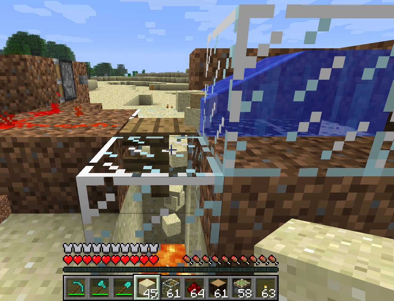

Working item button.
Thanks to official reelease version (1.0), now we can modify standart wood pressure plate to act like button in relation to dropped items. In previous non-development versions there were no way to automatically clear fallen item from pressure plate - pressure plate stayed "ON" until item disappeared by itself (after 5 minutes) or were collected by player. So all these secret buttons activated by dropping an item into the pit were semi-automatic, because you must manually retrieve dropped item to deactivate it. Now you can create fully automatic item button by placing pressure plate on a fence (that has now collision box just about the size of the fence itself): when item is dropped on the side of a pressure plate (but not on the center) it will pass through the plate activating it only for a split second (just like a standart button works).
Item button diagram: A - drop shaft; B - redstone output; C - disposal shaft.
To be sure that item will be dropped on the side of a plate, feed it to the plate using water slope instead of placing drop shaft directly above a plate. Also, fence connects itself to the solid blocks - bars can interfere with falling items. So be sure that you place non-solid block (like glass) on the side of the fence that is directly above water slope. And to be completely confident that item won't land on the fence after dropping from water slope (though, even with minimal length of slope at 2 blocks i've never encountered these) keep water level near the pressure plate as low as possible.
Mechanical to Redstone conversion
A Mechanical-Electrical Converter
Making use of a quirk involving the update function on blocks near a water or lava source, it is possible to convert the "mechanical" energy of updating a nearby block into a redstone signal. To do this, create a water or lava rig that will shift when the desired block updates (for more info, read this thread [broken]). Then position a redstone torch or powder trail so that the water/lava will wash/burn the torch or powder. Do this in such a way that the missing redstone component will change the input signal of your circuit.
Once this setup has been rigged, the next time an update function is called in an adjacent block to the water/lava source, it will trigger your mechanism. Update functions include: an adjacent block is placed by a user, gravel or sand falls into an adjacent block, grass grows, wheat grows, an adjacent block receives power, an item resting on an adjacent block changes state (such as a door being opened), or redstone ore is stepped on, destroyed, or right clicked.
This setup can only trigger once before needing to be manually reset.
See also: BUD switches which are more versatile.
Redstone to liquid kinetic conversion
A Redstone-Liquid Kinetic Converter
It is possible to use the same quirk described in the Mechanical to Electrical Conversion section to make water or lava flow as desired. In order to do this, simply follow the instructions in this thread[broken] and run a redstone wire to the block adjacent to the water/lava source. Whenever the redstone wire toggles state, the water/lava source will update. If arranged properly, this can be used to redirect water or lava whenever the desired input is given via redstone circuit.
Alternatively, as of Beta 1.7, pistons provide multiple-use liquid control. The piston plate in its extended position blocks fluids from any direction, as does a block attached to the end of a sticky piston. It is far easier to use a piston (or multiple pistons) to control fluid flow using redstone circuitry, especially since they do not need to be manually reset.
Detecting short or long signals
A signal length detector
Sometimes it is useful to be able to detect the length of a impulse generated by a Monostable Circuit. To do this we use an AND gate with redstone repeaters attached. These will only allow the signal to pass through if it has a signal length longer than the delay of the repeaters. This has many uses, such as special combination locks, which require you to hold down the button. It can also be used to detect Morse code, based on the principle that a dot will not make it through the gate but a dash will.
A signal length detector that blocks signals longer than the repeaters.
The circuit can be altered and used with a piston to create a reverse effect. Only a signal length shorter than the repeaters will pass. The piston is pulled back at the same time the repeaters are activated. As long as the input is on, the piston is back and the circuit is incomplete. If the charge reaches the end of the repeaters before the piston is pushed out again, the charge was too long and did not pass through. This can be used in sequence-dependent locks so other players cannot hold the lock open with torches. (doesn't work right due to the end of the signal always going through the block after it's pushed back)
Related pages
- Redstone
- Redstone (wire)
- Redstone (ore)
- Redstone Dust
- Diode/Repeater/Delayer
- Redstone Torch
- Advanced Redstone Circuits
- Mechanisms
- Traps
- Piston Circuits
References
| Help | |||||||||||||||||||
|---|---|---|---|---|---|---|---|---|---|---|---|---|---|---|---|---|---|---|---|
| Menu screens |
| ||||||||||||||||||
| Game customization | |||||||||||||||||||
| Editions |
| ||||||||||||||||||
| Miscellaneous | |||||||||||||||||||